Pressure Probes
Pressure probes can be used measure the stagnation pressure, the static pressure, and the flow angle within a fluid stream. When designing a pneumatic probe that is to be used in flow measurements, the effects of blockage, frequency response, pressure hole size and geometry, the local Mach and Reynolds numbers and the relative scale of the phenomena under investigation must be addressed. In general, better accuracy is obtainable if smaller probes and transducers are used though this usually means that the mechanical integrity may be compromised, that the response times are longer and that there are greater problems with contamination in dirty environments. The effects of blockage become greatest when the flow is compressible. For example, inserting a probe into a gas stream where the undisturbed Mach number is 0.9 will cause the flow to choke if the flow area is reduced by only 1 percent. In supersonic flow, a probe stem can create a detached bow shock that lies far upstream of the probe tip.
Static pressure probes are sometimes used to obtain static-pressure measurements in the flow rather than at the boundaries. A static pressure probe may simply be a cylindrical tube placed parallel to the flow with static tappings located on its body. A variety of nose configurations can be used on the static tubes. Some of these probes are known as wedge probes, cone probes, disc probes, and Prandtl tube probes. For all of these, the static pressure readings obtained are influenced by a number of factors just as in the case of the wall static tappings.
Since the accurate use of static pressure probes requires that the flow is parallel to the axis of the probe, their use is best restricted to flow fields where the gradients and turbulence are small. These conditions are rarely fulfilled in turbomachinery research rigs except at the inlet to the test sections. Here, the static tubes are often combined with stagnation pressure tubes in order that the stagnation pressure and flow velocity can be determined.
If a half-open tube is placed so that its open end faces the oncoming flow stream, then the stagnation pressure of the flow stream can be measured at that point (Pitot, 1732). Inevitably, the probe will disturb the flow near to the measurement point but in uniform steady flow, the stagnation takes place quite rapidly in the vicinity of the nose so that heat transfer and frictional effects (Hurd et al) can be ignored and almost any size and form of tube will correctly measure the stagnation pressure providing its axis is aligned with the flow direction. However, if the probe is in a steep stagnation-pressure gradient field, such as occurs inside a the boundary layer then the streamlines are deflected toward the region of lower velocity. This deflection causes the probe to indicate a stagnation pressure higher than that at the probe centre location.
When the stagnation-pressure probe axis is not parallel to the flow direction an error in the measurement will result. The degree of error is determined by the nose shape of the probe. Cylinder type probes possess very little tolerance to misalignment. Kiel probes can tolerate variations in flow angle to 45 degrees. A deeply bevelled Pitot probe can remain insensitive to within 1 percent of the dynamic pressure over an angle of as much as 25 degrees.
Pitot probes, beside being influenced by a variation in flow angle, turbulence, pressure gradients, and probe nose geometry are also affected by Mach number and by probe support body geometry and by fluctuations in the flow field (Grant).
Changes in flow direction in turbomachines are directly related to the work interchange. An accurate knowledge of the flow direction is therefore very important. Pressure probes that are sensitive to flow direction are used for this purpose. The probes are usually calibrated to determine the effect of their orientation to the flow on the measurement. The calibration is most often performed in a free-jet formed by placing a nozzle at the exit of a large plenum chamber. To determine the effects of pitch and yaw, the test probe is rotated about its axes. The pitch and yaw angles are defined in the figures below.
The most common of the pressure sensitive direction probes are the cobra, the wedge, the five-hole and cylindrical probes some of which are shown below. In all of these designs one or two pairs of symmetrically constructed pressure tappings are inclined with respect to the flow stream. When only one pair of pressure tappings is used, two-dimensional flow direction measurements are obtained; two pairs are used for three-dimensional measurements.

A 5 hole truncated pyramid probe
Flow direction can be determined by either of two methods. The first is the null method. With this method, the probe is mounted in an actuator, and the flow angle determined by equalising the pressure reading obtained on the two opposite static tappings. With the second method, the probe is mounted in a fixed position and the individual static pressures measured. By means of prior calibration, the flow direction can be deduced. The latter method must be used when the probe cannot be rotated while maintaining the tip at a fixed spatial location.
The cobra probe is usually constructed with three tubes soldered together side-by-side, facing into the gas stream. It is therefore used to determine only one flow angle (typically the yaw angle). The centre tube is used for stagnation pressure measurement; the two outside tubes have their forward tips cut off at 45 degrees. All three tubes lie in single plane. The cobra probe is widely used for flow angle studies because of its low blockage and relative ease of manufacture. It should not be used to measure the dynamic pressure or to infer the static pressure, primarily because the difference in pressure between either of the side holes and the centre hole is a relatively small fraction of the dynamic head.
The wedge probe (see below) is a simple, rugged, two- or three-dimensional probe that consists of a triangular, prismatic probe. Unlike the cobra probe, the wedge probe can be used to measure the static pressure. It has been made with various angles, the most popular being between about 8 deg. and 30 deg. The upper limit to the useful operating range of Mach numbers is a function of the angle and the flow pitch angle. It is lower for probes with greater included angles. Narrower wedges are, however less sensitive to flow angle but they do offer better accuracy in terms of static pressure measurement.
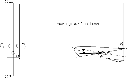
A 3-hole Wedge Probe for yaw and pitch measurement
Five-hole probes are a development of the two-hole Conrad and three-hole Cobra probes. They are used to measure the pitch and yaw angles of the flow, the stagnation pressure and dynamic or static pressure. As such, they provide sufficient data to fully specify the velocity and pressure fields providing that the stagnation temperature and so, the density, is known. Very few turbomachine flow fields are not three-dimensional
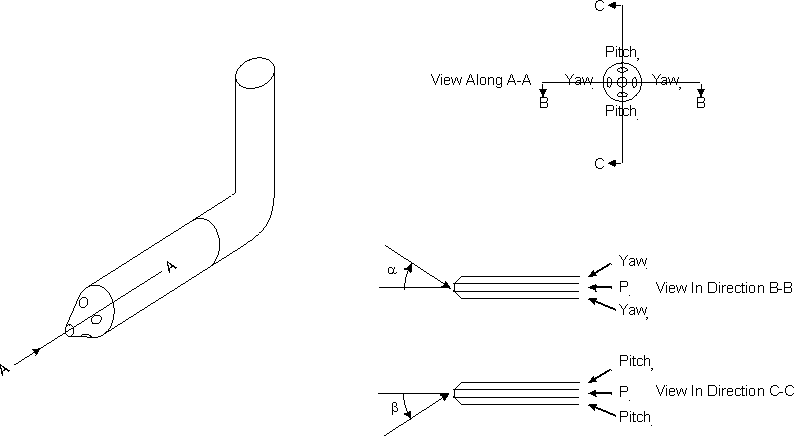
A 5-hole truncated cone probe
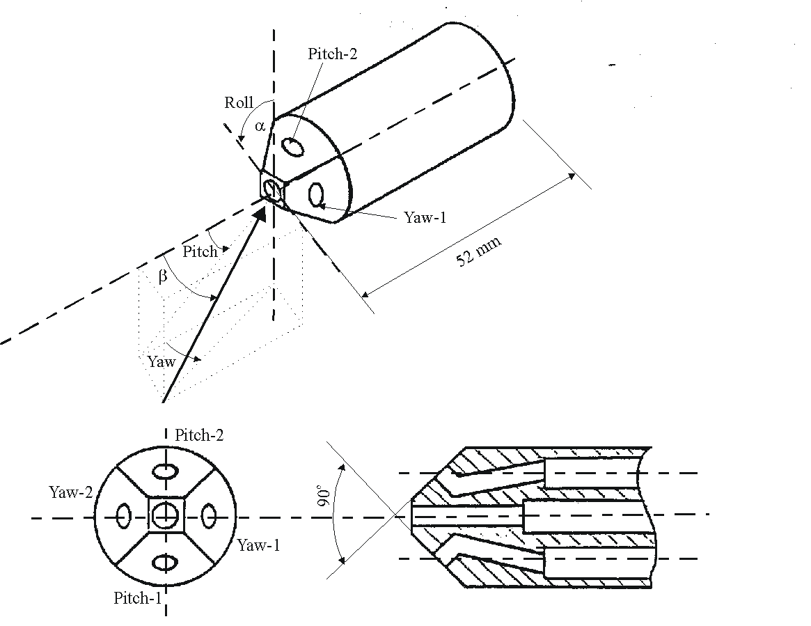
A 5-hole truncated pyramid probe
The figures above show typical five-hole probe geometries. Typically, the included angle of the probe nose varies between 60° and 120° . The greater the included angle, the less sensitive the probes are to the dynamic pressure but the more sensitive they are to changes in flow angle. In practice, an angle of 90° provides a reasonable compromise. All of these probes are remarkably insensitive to the effects of Mach number but some are sensitive to Reynolds number changes. The 5-hole truncated pyramid probe is least sensitive to changes in Reynolds number.
In reality, only 4 pressure measurements are required to determine the static and stagnation pressures and the two flow angles. The figure below shows a probe that takes advantage of this fact.
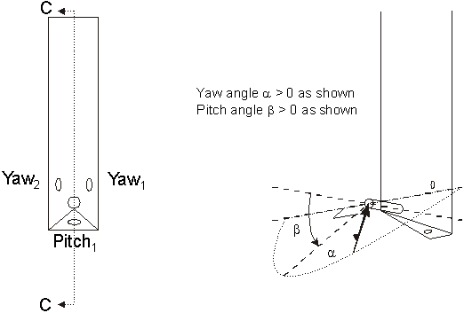
4-hole Wedge Probe for yaw and pitch measurement
The calibrations are normally carried out using the Transonic Cascade Test Facility of the Whittle Laboratory. This is a closed circuit, variable density (0.04 < r < 3.5 kg/m3) wind tunnel in which the Mach number and Reynolds number can be varied independently while the temperature is maintained at approximately ambient conditions.
For the purposes of the calibration, the working section is fitted with a half-open rectangular nozzle (see below). It has upper and lower walls that are porous (see drawing). This enables operation at supersonic conditions since, as the back pressure is lowered below the sonic value, suction through the walls begins to take place. This allows the flow within the walls to expand and reach supersonic conditions. The height of the nozzle is 83 mm and the width is 101.6 mm.
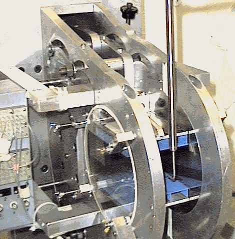
A 5-hole cone probe undergoing calibration
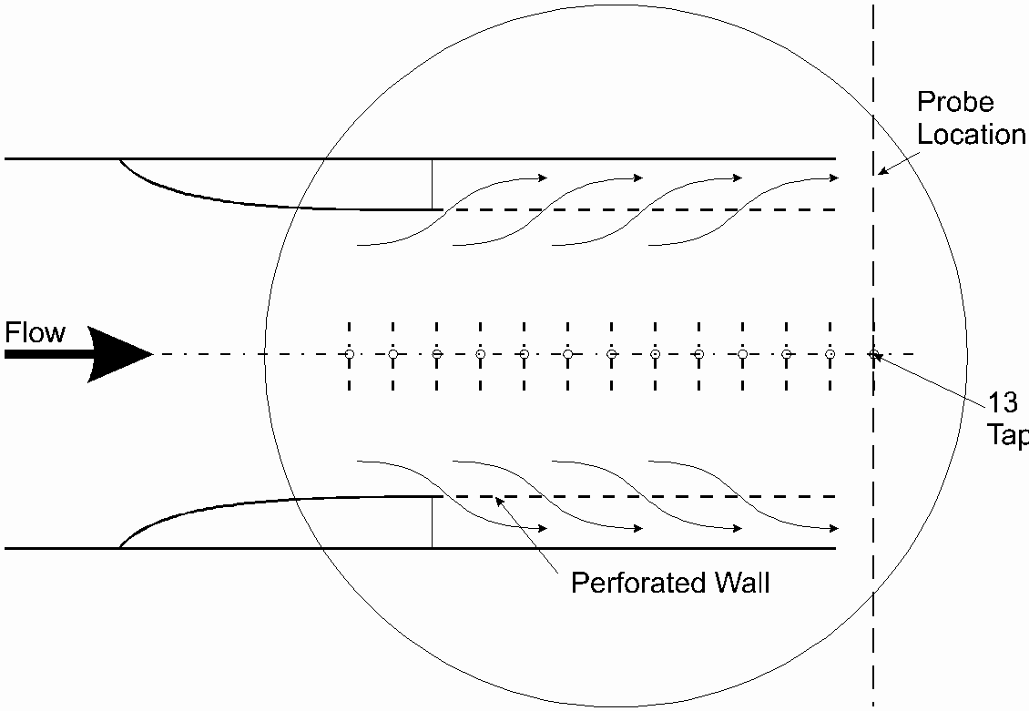
The supersonic calibration tunnel
A Schlieren photograph of the supersonic flow is often taken to check the quality of the tunnel flow.
The use of multi-sensor fast-response pressure probes is now relatively common place. Unfortunately, the size of these probes is often larger than is ideal. It is for this reason that single sensor probes are sometimes used in investigations of unsteady flow. In use, the single sensor probe must be placed at a number of different orientations to the flow, often by simply rotating the stem of the probe mount. The run time of a given experiment increases in proportion to the number of orientations employed. Furthermore, the number of orientations is usually more than is strictly required due to poor conditioning of the experiment so that a significant amount of redundant information is available and run-time costs are increased. However, a data reduction technique that reduces the run time cost of using single sensor fast response probes to the minimum is available. This is achieved by using all of the data obtained in the experiment so that there is no redundancy no matter how many orientations are employed. The method relies on comparing the measured data with the calibration data in order to obtain a best fit between the two datasets. It relies on the method of least squares

A fast response pressure Probe based on a commercial sensor
Home | Current Research | Research Opportunities
Publications | Staff and Students
Research Facilities | Travel Information | Contact Information | Links