| © CMG Lee • Dec2003 | |||||||||||||||||||||||||||||||||||||||||||
| Home | Basic 3D | Projection | Holographic | Optical addressing | Flat panel | Survey | Accommodation | Autostereo | Perspective | Principles | Simulation | Cam Display | References | ||||||||||||||||||||||||||||||
|---|---|---|---|---|---|---|---|---|---|---|---|---|---|---|---|---|---|---|---|---|---|---|---|---|---|---|---|---|---|---|---|---|---|---|---|---|---|---|---|---|---|---|---|
 and distance
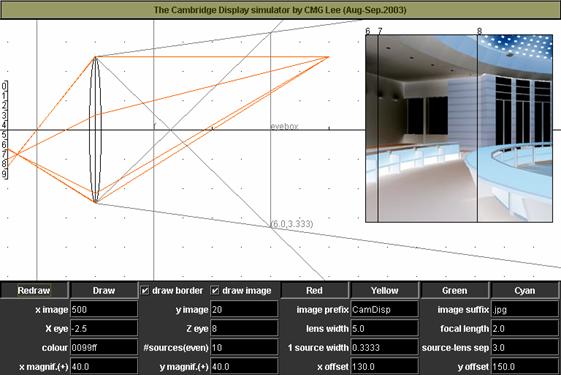
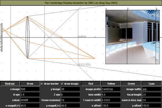
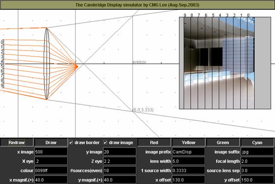
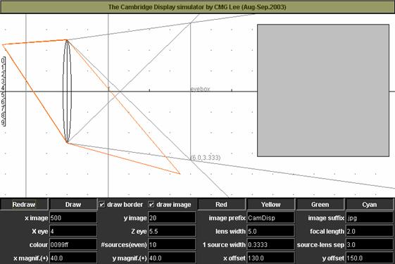
 in front of the field lens.

| Copyright CMG Lee & ARL Travis, Photonics and Sensors Group, Cambridge University Engineering Department |