The Statical Equilibrium of Plane Frameworks
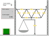
Three triangular frameworks made of steel, aluminium and CFRP, assembled with different fabrication techniques are tested by the undergraduates at CUED each year, in the Structures Laboratory. This is a simulation of that experiment.
Load the structure by dragging and dropping the weights. The strains on each of the members can be read by placing your mouse cursor over the relevant strain gauge. These record the change in axial length of each member under load. All the gauges have the same calibration factor.
Virtual Experiment Instructions
Please make sure you have a copy of the experiment instruction document.
- By using a free body diagram, determine the relationships between the pan load, P, and (i) the reaction force, R and (ii) the load applied to the frame, Q (section 2 of the experiment instruction document).
- By using free body diagrams at each joint, determine the theoretical forces as a function of applied (pan) load in each of the 12 members, noting the symmetry of the structure (section 2 of the experiment instruction document).
- Calibrate the load cell (strain gauge 1) by plotting digital strain read-out as a function of load for the load cell for each framework (section 5 of the experiment instruction document).
- Investigate the linearity of strain by plotting digital strain read-out as a function of load for at least 2 members of each framework (section 5 of the experiment instruction document).
- Calculate the theoretical forces for the 2 members in each structure investigated in 4 for an applied load (Q) of 5kN.
- Compare the results of 5 with the measured (interpolated) forces in the 2 members for an applied load of 5kN. Consider the reasons for any differences.
- Consider the effect of mass, Young's modulus and cost on the performance
and economics of each structure by constructing appropriate figures of merit.
Dimensions of the structure required for 7:
Frame Member CSA Mass Al 952 mm2 39 kg CFRP 339 mm2 17 kg Steel 406 mm2 43 kg

