 |
Arbeitsberichte des Institut fuer mathematische Maschinen und Datenverarbeitung (Informatik)
Friedrich Alexander Universitaet Erlangen-Nuernberg
Band 16, Nummer 9, Erlangen, April 1983
THE DESIGN OF MECHANICAL COMPONENTS
AND THE DEVELOPMENT OF DUCT:
17 YEARS OF CAD/CAM IN CAMBRIDGE UNIVERSITY
Abstract
The Cambridge University Computer Laboratory acquired a PDP 7 computer in 1965. The Cambridge University engineering Department formed a joint team with it at the end of the year and started to investigate the design of complex components requiring patterns, moulds and dies for their manufacture.
This paper discusses the approaches to the problem, which resulted in POLYSURF, ROMULUS and DUCT as commercially available systems.
The paper also discusses two fundamental theoretical problems; in design, the question of how to optimise for minimum weight, maximum strength, optimum flow etc.; in manufacture, the questions of the existence of parting lines and of whether an object can be made.
Finally, the question of the desirable features of a CAD/CAM system are discussed both from an economic and from a technical point of view; examples are shown of how far DUCT meets these requirements.
1 Introduction
The academic world has had little to say about the design of components requiring patterns, moulds and dies largely because most such components could never be described uniquely and were therefore beyond the scope of mathematical analysis. What was probably the first attack on the problem of describing objects with a ghost line, Fig.1, was made by A R Forrest in 1966 at my suggestion.
|
My interests in this problem was awakened early in 1965 when I was planning a post graduate course in Cambridge University Engineering Department on the theory of design, intended for designers from industry with some years of experience in design since their first degree. I recognised that while I myself could design detailed components on the drawing board, I was unable to describe the logic of what I did. If you examine recent work on systematic design, such as that by Pahl and Beitz you will discover that much work still needs to be done on this problem. Listening to a lecture by Strachey in March 1965 on the early work on CAD at M I T by Ivan Sutherland and others I recognised that if we had to wrestle with the programming of computers for this purpose, we might arrive at an understanding of the logic behind what we did, since computers are purely logical devices.
This lecture is intended to describe some of the work that has been done by us in Cambridge, and to point to some fields of work which are still largely untouched.
2 The Fundamental Problems
2.1 The roles of Designer and Patternmaker
 |
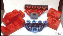 |
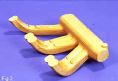
Few designers, unless they themselves have worked as patternmakers, fully understand the problems involved in describing the blend areas – Figure 2 – or the parting lines – Figure 3 – in objects which they design. Most drawings of complex components are (i) wrong, (ii) over dimensioned, and (iii) under dimensioned ! The reason is quite simply that few 3D objects with complex surfaces can be described uniquely in 2D. Designers would usually do much better to give only essential dimensions, and to leave the rest to the patternmaker. The difficulty is that draftsmen believe that they are paid to draw ! From the drawing in Fig. 4, three different patternmakers made three different patterns, all correct to drawing. One gave engines with 5% better fuel consumption. Normally components, as designed by conventional methods, cannot be fully analysed, if for no other reason than that the parting line is uncertain, and the draft angles are not fully designed. Having developed DUCT as a CAD/CAM system capable of handling these problems, we have found that young patternmakers learn to use it more readily than do draftsmen, because the patternmaker has a greater insight into the problems to be solved.
 |
2.2 Blending
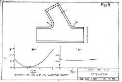
Forrest tackled the problem of Fig. 1 without success: much later A R Johnson showed that for this particular problem a unique mathematical solution exists, which can readily be generalised to yield answers to one of the designer's optimisation problems, how to design for minimum weight. The results in Fig. 5 show that minima do indeed exist, a fact which is not self evident, but that they are very flat, and consequently designers might usually do better to design not for minimum weight, but for minimum scrap in the foundry e.g. with twice the blend radius needed for minimum weight. A lot of systematic work is still needed to provide detailed guide lines for designers.
Weight of course is not the only criterion, and similar analytical work is needed for stressing, fluid flow, manufacture etc. Testing is now possible since finite element (FE) meshes can be generated for such objects ( Fig. 6).
 |
 |
2.3 Parting lines
No book on descriptive geometry discusses the problem of parting lines, and what are the conditions under which one can be found. The problem was first discussed by Dr. D P Sturge (Ref.4) who showed that two basic design components, frequently used by draftsmen, cannot in general have parting lines. These shapes are the doubly bent cylinder and the cone, Fig. 7 and Fig.8. I find it surprising that the geometers of the last century never discussed the general problem. The fundamental question is that of knowing when a horizon line is also a parting line. While Dr. Sturge has written programmes to help the designer to find split lines and surfaces, these cannot in general be found automatically, since the designer is faced with a choice as to how to distort the components from the desired shape.
 |
 |
3 Alternative systems of CAD
Critical evaluation of the various systems of CAD shows that almost without exception they have been developed to replace the work that is currently done in the drawing office, not what is done in the design office. As long ago as 1966 I argued (Ref.5) that the great potential which CAD offered was to abolish the drawing office and to put the whole of design in to the hands of skilled designers. This concept has underlain our work in Cambridge, which has followed three major routes.
3.2 Surface description
The work of S A Coons (Ref.6) was the starting point for that of A R Forrest (Ref.1) and their work together at M I T during the long vacation 1966 decisively influenced the thinking of both men. A far stronger influence on our work was that due to P Bezier (Ref.7) whose book was translated into English by Forrest, and Anne Pankhurst, whose husband, R J Pankhurst, worked with us, and also for a long vacation in Erlangen. Although a great deal of the early work on splines was done by A W Nutbourne (Ref.8), we have to continued to prefer Bezier to the now fashionable B splines; properly handled they both give the same accuracy for circles.
Many people worked on surface description, and the work was finally taken over by the Government Computer Aided Design Centre in Cambridge, which developed it into and licence it as a system known as POLYSURF.
3.3 Volume modelling
By spring 1967 I was becoming disillusioned by the results which we were achieving with surface modelling, and suggested that the way in which designer's conceived of objects was not as a collection of lines, but as an assembly of volumes. As a result, I discussed this idea with C. A. Lang, at that time leading the Cambridge team, and with P. A .Mason, an experienced designer from industry, who was at the time studying on our post graduate course in engineering design methods. Fig. 9 shows the sketch made by Mason of the shapes with which he thought that he worked.
 |
The idea lay fallow for lack of someone to work on it, but was finally picked up by I A Braid (Ref.9) and was both generalised and brilliantly developed by him. This work is the basis of the commercially available volume modeller known as ROMULUS. Similar concepts were developed at about the same time by Professor Spur in Berlin and Professor Voelcker in Rochester, N Y.
Volume modelling as it has been developed world-wide is relatively primitive, since it starts from simple geometric forms which are then sometimes distorted. Because of the simple geometries, they can handle hidden line removal etc relatively easily. DUCT, the system discussed below, differs from it in that Duct starts with surfaces looking like volumes, often of a high degree of complexity, and these can be readily manipulated. Just because the geometries are in general complex, finding intersections of two generalised DUCT surfaces requires very large amounts of computing.
3.4 Spine and cross sections: the Duct concept
3.4.1 The Origins
In 1969 the Ford Motor Company Ltd. seconded one of its staff, Stanley Matthews, to work with our group. He had been the first engineer in Ford UK to use a computer, but was now close to retirement. He commenced by using our surface system, which was admirable for car body work, but utterly unusable for components such as inlet port cores or almost any other component to be found under the bonnet of a motor car. Matthews proposed that we ought to design as draftsmen do, using centre lines and cross sections normal to them. For this purpose he proposed to use Nutbourne's (Ref.8) splines to allow generalised 3 D centre lines, and piecewise Lame ovals (anxn + bnyn = cn ) or:- [a to the n th times x to the n th] plus [b to the n th times y to the n th ] equals [c to the n th ] ) to provide cross sections. An example of this, Fig. 10, in the system as developed by P J Payne, shows the astonishing range of sections obtainable.
 |
The first object to be cut using the DUCT system was a jug shape at the Machine Tool Exhibition in London in August 1972. At that time we understood nothing about offset surfaces, so transitions were somewhat uncertain.
The system came to be called DUCT one day while we were discussing Matthews’ and Payne’s work, which at that time was concerned entirely with engine ports and manifolds. I suggested that these were all duct-like and the word stuck. I have since on occasion pretended that it stands for Design Using Cambridge/Computer Technology since we came later equally well to describe open surfaces. With a little more foresight we might have called it CAMDUCT, Computer Aided Manufacture and Design Using Cambridge Technology ! Its basic concepts are shown in Figs. 11, 12 and 13.
 |
 |
 |
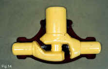
3.4.2 Castings as an Assembly of Holes
One interesting concept which only developed later was that just as for castings only the female of the outside of the pattern is of interest, so for many objects such as a cylinder block of a car engine the holes are what matter, not the metal. They are often easier to design, Fig. 14.
 |
4. DUCT – A fully integrated CAD/CAM System
4.1 The Fundamental Concept
We were developing a system for designing, analysing, and making components, not merely for drawing them. It had therefore to provide unique piecewise analytical descriptions of components allowing the information to be used:
(a) for optimisation either by direct calculation, e.g. volume calculations, or by FE mesh generation and analysis, and
(b) for manufacture
I had not at the time recognised the problem inherent in the necessity to find parting lines. DUCT was radically reconceived and rewritten using 3 rd. order Bezier curves by T H Gossling (Ref.10), the work commencing in December 1972. In discussing the targets to be achieved we recognised certain essential engineering and commercial requirements.
We should develop a system which was no more difficult to use by a draftsman that was a drawing board, since industry has got to work with the men it has available. A draftsman needs some three years to train to use conventional methods, and I suggested that he might expect to have to spend 3-6 months being retrained to use DUCT. Unfortunately firms expect computers to act like magic wands, and do not like systematic retraining.
The system was intended to enable design and manufacture to be determined completely by the designer, without the need for patternmakers or toolmakers. Since it had to compete with them it had to be cheap to use: the finished object had to compete on price.
The system was to enable a designer to work ab initio: it was not to be a system (as is APT) for interpreting other people’s conventional drawings. Conventionally, designers work with straight edge and compasses, which rarely give the best solutions for 3D work. We were to offer the designer the possibility of using better transition curves.
The patternmaker knows nothing about 2 nd. order continuity of surfaces, i.e. of curvature, but only of 1 st. i.e. continuity of tangent. The system could be simplified if we acknowledged that we were not trying to satisfy completely the rare engineering occasions where 2 nd. order continuity matters. Hence 3 rd. order Bezier curves were acceptable. The system must be available time-sharing, since at that time the mini-computer was only a glint in peoples’ eyes. The average size of a pattern making shop throughout the world is about 8 men, and even the largest in Europe, employing 225 men, did not want to buy a computer and license the programs, as well as having to buy 3D numerically controlled machine tools.
This requirement has already been overtaken in part by changing cost and simplicity in use of computers.
4.2 Some Consequential Decisions
4.2.1 Graphics Display
Many workers in the Cambridge University Computer Laboratory had collaborated to develop GINO as a research tool to investigate all the possible ways of using displays to produce graphics information. This system has since been further developed and licensed by the Computer Aided Design Centre. For our purpose it was too large and too clumsy so my colleague, Dr R B Morris, wrote a graphics package which would run on an IBM 1130 with 8k core, something which most people at that time (1973) said was impossible.
4.2.2 Choice of Computer
Thanks also to Dr R B Morris, we had for some years unlimited free time on a large time-sharing bureau. We therefore started development of DUCT on it, and later, after it had been taken over by Control Data, continued to work on the time-sharing bureau now owned by it, so that the system could be available to anyone with a telephone. Firms could thus avoid buying their own computers.
4.2.3 Program compartmentation and the use of OPTIONS
The use of a large computer led those developing the program into the temptation to using all of its facilities and thus making the system expensive to use. To avoid this the system was compartmented, Fig. 15, and much of the development done on our 8k IBM 1130. This allowed a very simple command system to be used, but was inconvenient in that the users had to move frequently between options. Cheapness in computing was important, since the overheads in the pattern- making industry are very low, and unless its prices could be met, firms were largely uninterested in the technical advantages of DUCT.
 |
4.2.4 Choice of Terminal
The need to keep down capital costs for small firms led to a great deal of hard thinking about workstations. In 1974 we adopted a terminal developed by PERA consisting of a Tektronix 4010 screen with an on-line plotter driven by a PDP8 computer: this cost £12,000, while at that time the cheapest 3 axis n.c. machine tool made by Beaver also cost £12,000
4.2.5
Wanting a smaller and cheaper plotter we brought a Tekronix 4662 plotter when it came out, and quickly discovered that working on a 300 or 1200 baud line it plotted as fast as did the screen. We then found that when designing complex components it offered great advantages since coloured pens could be used, and measurements of lengths and angles could be taken off the drawing. It could also be used as an input device, so curves could be sketched and input to the design.
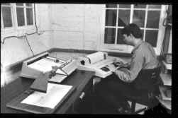
The preferred terminal now became the Tektronix 4662 plotter, together with a printing terminal to give a continuous record of all work done. This can be run at up to 1200 baud. As a result the basic terminal cost – Fig. 16 – today (1982) is about £4,000 (or with tape preparation equipment as well £7,000) while the most basic 3-axis n.c. Machine tool is about £21,000. The changing ratio of costs since 1974 is striking, and is likely to continue.
 |
With an in-house computer a small screen working at 9600 baud is also useful but is not essential when DESIGN work is being done, as opposed to DRAWING OFFICE work.
4.2.6 Stereoscopic Viewing
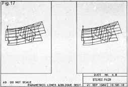
Hidden line removal is costly and throws away good information. Dr. R B Morris included in his viewing package the facility for producing stereo views of drawings, Fig. 17. The additional information is invaluable to the designer. Unfortunately about 20% of people have monocular vision.
 |
4.2.7 Dimensioning
Since the computer produced tables of dimensions and since drawings often need to be dimensioned differently for different purposes, such as for making assembly drawings or for inspection, we did not bother with dimensioning, more particularly since DUCT would normally need to be associated with normal 2D drawing office system, many of which were being developed. In retrospect this was probably a mistake, not so much technically as commercially, since people like to see done what they are used to, whether it is relevant or not !
My views on this were strongly influenced by having worked in my younger days in a very progressive firm which often used tables of dimensions. I ought to have paid more attention to ordinary ones !
Recently limited dimensioning has been added in DUCT Mark 4.
4.2.8 Front End
For similar reasons we did not bother to produce a front end, since we wished to discourage designers from using arcs of circles and straight lines, but to encourage them to use Bezier curves where possible. Conventionally a draftsman, if he uses a French curve, then proceeds to approximate it with arcs of circles, often forgetting to dimension them adequately. We wished to persuade him to use what are effectively 3D French curves. When machining, an impulsive acceleration occurs where a tangent meets an arc of a circle. This degree of didacticism was a mistake on my part which we are currently trying to make good.
5. Development of the DUCT system
5.1 Making objects
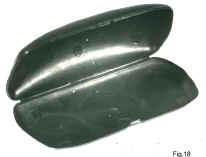
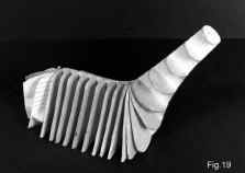
As early as 1974 firms were being persuaded to allow us to design and make objects for them. An example of this is the spectacle case tool in Fig. 18. This taught us that we must learn to design closed DUCTS with ends, as well as open ones. The complete solution to this problem was only produced in 1978, when P. W. Olding realised that an object such as the golf club head, Fig. 19, needed to be designed with 2 spines, the rounded tip having a semi-circular one. This also taught us how to imitate strickle pattern-making, and to enable DUCT to be used for manufacture without an n.c. machine tool.
 |
 |
5.2 The split or parting line problem
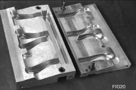
In 1976 we redesigned an inlet port, Fig. 20, for British Leyland, and for the first time discovered that many designs are unmakeable in mass production, since the draftsman has not properly designed the split line, but has left the problem to the designer. Shown our redesign of the component in DUCT using the original conventional drawing for the essential data, we had difficulty in convincing the pattern maker that that was what he required, and that we had had to take cognisance of what a pattern maker does. Only when component was machined was he convinced.
 |
Finding a possible split line proved to be extremely difficult and time consuming until at the end of 1977 Dr D P Sturge recognised the fundamental problem underlying it, and wrote the appropriate program.
5.3 The Blend problem
This had been the starting point for our work. A first solution suited to the manufacturing of symmetrical blends was programmed in 1975 by E. B. Lambourne,(Ref.11) on secondment from the Delta Metal Co Ltd to do an MSc degree, using an idea produced by Dr R B Morris. A general design and manufacturing solution was first proposed and implemented in 1980 by Dr M. Galwelat (Ref.12) which enabled one DUCT to be blended into another DUCT either using arcs of circles or Bezier curves. The basic idea, so that the blend should itself be a DUCT, was to take the end section of a branch DUCT, and to use it as the spine for the blend, Fig. 13. The program also allowed true intersections of a cone or prism with a duct.
5.4 Variant Design
Ducts can be stored and recalled at any time, so that what is called "Variantenkonstruktion" in the German literature is very simple. A duct can be shrunk differentially, moved, and rotated, Fig. 21.
 |
5.5 Licensing
Marketing a product such as DUCT is not a job for universities, nor for the amateur. We therefore licensed DUCT in 1978 both to Delta CAE Ltd and also to Control Data. Early in 1981 we also licensed it to Compeda Ltd. All grant sub-licenses, while the University sticks to development.
6 DUCT Mark 4
6.1 User Experience
Tests of DUCT Mark 3.1 by VW in 1979 produced a large number of new requirements and ideas, while steady use by Delta, and also in time-sharing by Daimler Benz, produced a flood of useful suggestions. Some represented a few hours work to implement, other man-months of development. Many of these could be embodied into Mark 3.3, but in the autumn of 1980 Dr D. P. Sturge and M. S. Nicholls called into question the whole concept of keeping our compartmented or ‘option’ system intact. Users wanted the convenience of use offered by having the whole system available simultaneously. The attitude of the designer using the computer daily and of the system developer only occasionally using the system for serious design, are very different
Furthermore, the cost of computing had dropped radically. On Control Data, time-sharing costs had dropped between 1970-1980 by a factor of about 3 in real terms, although this had to some extent been offset by rising telephone charges.
Computer costs had also dropped, and transportability of programs increased. Two of our licensees were using Prime computers, and in December 1980 we were able to acquire a Prime 300, more recently converted to a Prime 250. Small firms were getting used to the idea of owning computers, and one firm employing only 180 men had bought a PDP 11/23 and one of our licensees had implemented DUCT on it. This change of attitude both to owning a computer and to paying licence fees for programs was of great importance.
6.2 Development of DUCT Mark 4
The Mark 2 and Mark 3 versions of DUCT represented improved and upward compatible geometries, Dr D. P. Sturge being responsible. In Mark 4 the changes in geometry represents only minor improvements, but Dr D P Sturge and M S Nicholls (Ref.13) completely rethought the command structure. The principles adopted were:
The programs are written in strict FORTRAN 66. The minimum requirement for implementation is that the computer should have 64k of addressable space for each user.
All commands are available simultaneously
To enable this, all commands are of the same general form consisting of:
ACTION + OBJECT + IDENTIFIER + MODIFIER
( VERB ) ( NOUN )
e.g. INPUT POINT 1 U10, V10
Not all commands need all these parts, but are used from left to right for as far as is necessary.
(iv) Commands may be entered in full ( this is good for demonstrations ! ) or abbreviated to save typing: e.g I POI 1 U10, V10
(v) All commands are typed, except that numerical data may be entered from the screen or plotter by a digitising cursor. For the advantages of keyboard over table see Jackson (Ref.14)
(vi) Any command entered at the terminal may also be stored in a ‘command file’ so as to keep a record of a work session. Alternatively a command file may be constructed separately outside the DUCT system. A command file may then be run at any time, either to reproduce the work of an earlier session or to carry out some particular function which is frequently required.
(vii) Duct includes ‘registers’ which may contain either a series of numbers or a string of characters. A register is filled either explicitly or by an ‘Input Register’ command or else automatically by the execution of some other command. The contents of a register may then be picked up by another command by entering the name of the name of the register into that command, rather than the numbers of characters explicitly. The use of registers overcomes the need to re-enter a number printed out by the system, or to enter the same numbers repeatedly in several commands.
(viii) DUCT includes ‘lists’ which provide the ability to execute a series of commands for each item on the list in turn. For example, such loops may be used to draw a series of oblique sections.
(ix) The modifier of a command may include an expression enclosed within brackets. The expression may contain a combination of algebraic, trigonometric, or vector operations, so that the system may be used as an on line calculator.
(x) A command may be made conditional e.g.
IF (expression) command …
The command is only executed if the expression following IF is positive.
6.3 Development Time
The whole of DUCT Mark 4, which comprises about 35000 lines of FORTRAN, was written in less than a year, including many interruptions to design and make objects using DUCT, by Dr D P Sturge and M S Nicholls. This included a complete rethink of roughing path strategy for n.c machining, and the provision of a 5 axis machining capacity.
6.4 Command files
The ability for the users to write his own command files makes variant design particularly easy. It has enabled command files to be written for cross-hatching, Fig. 17, for simple dimensioning, for metacentric heights for yacht design, for volumes of blends, etc.
6.5 Blending and Ribbing
The generalisation in Mark 4 of the concept of blending to allow it to be carried out from longitudinal lines, from oblique sections and from edges has provided a neat solution to a large new range of design problems, and by the use of command files has allowed blending into a multiplicity of surfaces.
7. Manufacturing: CAM
7.1 DUCT was conceived as essentially being a CAD system which was to have CAM facilities: yet almost all its users have wanted it in the first place as a means of interpreting conventional drawings for manufacturing purposes. The reason for this appears to be that designers say that they make drawings and from them components are made. The manufacturing side of the firm however complains bitterly about the manufacturing problems which these designs pose. Particularly do they do so in the mass production industries where patterns, moulds and dies have to be refurbished and replaced due to wear. Even if a master model has been made, the accuracy of copy-milling machines is generally not high, for a number of reasons, whereas n.c. machines give high accuracy. Too often DUCT has been used as a part-programming language.
7.2 When the Government gave monetary support to the WCIU to continue the development of DUCT, part of the arrangement was that two other bodies, also receiving governmental support, should develop the CAM side of the programs, since they had extensive manufacturing experience with n.c. machines. This arrangement failed to work, so that eventually the work was done by the team doing CAD. The reason for the failure was instructive and in my personal experience very common in the field of computer programming. Very few writers of programs seem to be able to agree that someone else’s program is adequate to do the job, and most want to tinker with any program to which they get access. This happened in this case. Instead of developing the CAM side they criticised the CAD !
7.3 Finish Machining
The basic problem of designing a cutter path or a finishing cut is straight forward, since it depends only on finding the surface normal to the component, Fig. 22. What is not simple is the full determination of collision conditions, and work remains to be done in this field. So far as we are aware the problem has not been solved by anyone, if the engineering limitation is accepted that the computation costs must be held to an acceptable level. This however is a problem which might vanish with ever increasing power and decreasing cost of computers
 |
7.4 Roughing Strategies
Duct Mark 3.3 has a simple roughing strategy which has limitations if used with hard materials. Mark 4 has a greatly improved one: we are however working on the problem of an optimised one. Here the basic problem is that to avoid variations in cutter deflections and to ensure a given accuracy of the finished component, the rate of metal removed during the finishing cut should remain as nearly constant as possible. The geometrical problems are complex.
7.5 3 and 5 Axis Machining
Superficial thinking suggests that if a pattern or die has to have a parting line, then it can be machined on a 3 axis machine. Deeper thought reveals that if a 5 axis machine is used then a smoother surfaces can be achieved more rapidly. Initial contacts with the pattern making industry had suggested that it could never afford to buy 5 axis machines, but large automobile firms can. However, tables offering two additional rotary axes can now be bought relatively cheaply to fit onto 3 axis machines. As a result, DUCT Mark 4 now produces CL data suitable for existing 5 axis post-processors.
8 Future Developments
8.1 Retrospect
A program has been developed over a period of 16 years which in retrospect seems to have had a very halting development. It probably contains about 35 man years of work on DUCT itself, together with another 15 man years of general development in the field of CAD. The clearest lesson which the work has taught has been that in this field a few outstanding workers can easily keep ahead of larger numbers of good but less gifted people. The other lesson that has been learned is not merely the need to set clear targets, but the need to make sure that those which are based on technological considerations are up-dated rapidly enough. In retrospect, too much emphasis was perhaps placed on cheap computing. Had industry picked up the work faster, this might have proved to be more important than it has in fact proved to be. The reduction in computer costs and the increasing power of computers is causing firms to lay more emphasis on ease of use and less on price cost.
8.2 Geometry
At the beginning of this work one ill-judged compromise was made in that we thought that the work based in curvature integration by A W Nutbourne (Ref.15) might provide a better base than that of Bezier. In 2D it would have done, and it leads into a very interesting concept in n.c. machining whereby the rotational axes become the primary ones, and the transitional axes become the secondary ones. The curves used are CORNU spirals.
This work has been further developed for surfaces (Ref.16), and its further development will be followed: but for the moment Sturge’s geometry appears to be the best available. While many books have now appeared on computable geometries, conventional books on descriptive geometry will need to be modified to take proper account of the problem of the split line.
8.3 Development for Design
Users of the system continually suggest new features that would be useful and these will by provided. The hope remains that as a result insight may be gained into the design process itself, and that in particular designers may be helped to work conceptually in 3D.
8.4 Development for Analysis of Engineering Problems
Very large numbers of engineering problems of the most varied nature have never been tackled by the academic world because the artefacts could not be described uniquely in mathematical terms and therefore could not be analysed. The way is now open to tackle these fields. A few examples are given below which can offer great challenges to universities. They demand close collaboration with industry.
8.4.1 Fluid Flow
Firms are now asking why pressure drops through DUCTS cannot be calculated. Problems such as this are said by the experts in fluid flow to be immensely difficult: But 17 years ago the same was thought about CAD !
8.4.2 Foundry and Plastics Technology
The problems involved in understanding the flow and solidification of metal in moulds is so great that one world famous firm cannot order duplicate tooling for its two foundries in the UK because its two managers cannot agree as to how the moulds should be gated, and the runners and risers laid out. Much practical experimental work has been summarised by Wlodawer (Ref.17) and a major research project has bee launched in the USA by Professor J T Berry at Georgia Institute of Technology. While a very large family of problems has to be tackled, such as liquid flow in the mould, the crucial question is concerned with solving Stefan’s equations for the moving solidification front.
The problems with plastics, with high viscosity and heat generation due to high sheer rates, appear to be even worse.
8.4.3 The Design – Manufacturing Cost Loop
What a detailed designer or draftsman puts onto paper decides the cost of the component. In good design offices the works planning staff is always consulted before a component drawing is released for manufacture, but rarely is enough thought given to costing until too late.
Professor K Ehrlenspiel in the Institut fur Konstrukionslehre in the Muenchen TU has started to work in the field of closing the design-costing loop, and has already written programs enabling a designer to cost turned components and in particular to make sure that his attention is drawn to the cost-savings available by removing given features. He is now starting work on doing the same for castings, using DUCT, which is available on his institute computer, to describe the objects. The effect of this on design might be profound.
8.4.4 Finite Elements
An FE mesh generator is already available in DUCT, but work needs doing to improve it into a self-optimising mesh generator so as to minimise computing time and costs which can be heavy.
Work is also needed on programs to make use of FE to optimise designs for all the variables that may occur such as stress, strain, weight and fluid flow. Strain can be of great importance in the design of plastic containers such as bottles, when filled volume is required.
9 Conclusion
In conclusion, I wish to thank all those who supported and worked on DUCT. Without financial support from the Department of Industry Mechanical Engineering and Machine Tools Requirements Board, the Pye Trust, the Wolfson Foundation, ITT and The Delta Metal Co Ltd, DUCT would have been impossible. DUCT was conceived and developed by S. Matthews, P. J. Payne, Dr R B. Morris, A .W. Nutbourne, T. H .Gossling, P. W. Olding, A .L .Johnson, E. B. Lambourne, A R.Johnson, Dr D P. Sturge, M. S. Nicholls and A.M. Uttley. Without our superb technicians R. A .Jarvis, R. Ward and D. R.Miller, tools would not have been cut so efficiently. Moral support and the placing of orders by G.M.A.Cox of G. Perry & Sons Ltd of Leicester and J. J. Harvey (Manchester) Ltd among others gave us the opportunity to try out our ideas on many real components. My secretary Mrs S. J. Wolfe and her assistant Mrs M. R. Dolman have proved indefatigable.
The rights of DUCT are vested in Lynxvale Ltd, which covenants its profits to the University of Cambridge. It is licensed to Control Data, Compeda Ltd and to Delta CAE Ltd all of whom grant sub-licenses.
Transcribed by Paul Brennan
REFERENCES
1. Forrest, A. R. Thesis for Cambridge University 1968 "Curves and Surfaces for Computer Aided Design"
2. Pahl, G. & Beitz, W. Konstruktionslehre (Springer 1977)
3. Johnson, A. R. & Welbourn, D. B. "The Design of Detailed Components" (Engineering, Jan 1979)
4. Johnson, A. L. & Sturge, D. P. "The DUCT System of Design & Manufacture for Patterns, Moulds & Dies" ( MATADOR Conference 1979)
5. Welbourn, D. B. "The Use of Computers with Graphical Input/Output"
( CME Nov 1966 )
6 Coons, S. A. "Surfaces for computer aided design of span
forms"
( Technical Report MAC-TR-41 MIT June 1967 )
7. Bezier, P. "Emploi des Machines a Commande Numerique ( Masson, Paris 1970)
8. Nutbourne, A. W., Morris, R. B. & Hollins, C.M. "A
cubic spline package"
(Computer Aided Design, 1972 Vol 4 No 5 and 1973 Vol 5 No 1)
9. Braid, I. A. Thesis for Cambridge University 1973 "Designing with Volumes"
( Technical Report MAC-TR-41 MIT June 1967 )
10. Gossling, T. H. "The DUCT System of Design for Practical Objects" (World Congress on the Theory of Design and Mechanics (Milan) 1976
11. Morris R. B. & Welbourn D.B. "Computer Graphics and Numerically Controlled Machine Tools for Pattern, Mould & Die Production" (MATADOR 1975)
12. Galwelat, M., Sturge D. P. & Welbourn, D.B. "Blenden, Durchdringungslinie und Abwicklung" (Konstruktion 33 (1981) S.10)
13. Sturge, D. P. & Nicholls, M. S. "Developments in the DUCT system of Computer Aided Engineering" (23 rd MATADOR Conference Sept. 82)
14. Jackson, R. H. "The Application of CAD/CAM in a mechanical engineering company" (Electronics Power Jan 1981)
15. Nutbourne, A .W., McLellan, P. M. & Kensit, R. M. L. "Curvature Profiles for Plane Curves" (Computer Aided Design. July 1972)
16 Nutbourne A W "The Shape Matrix of a Surface" Cambs.Univ.Eng.Dept. Report CUEDIF-CAMS/TRI84
17. Wlodawer R "Gelenkte Erstarrung von Gusseisen" (Giesserei-Verlag 1977)
FIGURES
1. The fundamental problem of the pattern maker's thumb.
2. Core for inlet manifold with 4 blends, split line and draft angles.
3. Tooling and casting for British Leyland Manifold.
4. Typical port core drawing.
5. Relation between design and weight.
6. Finite Element Mesh.
7. Split line problem.
8. Split lines on core.
9. The original DUCT concept.
10. Original DUCT Modelling Concept.
11. Basic Closed Duct.
12. Basic Open Ducts.
13. Three types of BLEND.
14. Stop valve as difference between holes.
15. Options in DUCT Mark 3.3.
16. Basic design terminal including stereo viewer (operator: M.S. Nicholls).
17. Stereo Pair, oblique section and cross-hatching using DUCT Mark 4.
18. Spectacle case using DUCT Mark 0.
19. Prime No. 5 Wood, showing the strickle pattern-making technique.
20. Typical core box showing split surfaces.
21. Variant design and blend.
22. Finish cutter path and commands to produce it with DUCT Mark 4.
|
The Engineering Faculty of the University of Erlangen
decided at its meeting on D B Welbourn, Master of Arts Director in Industrial Co-operation University of Cambridge |
Citation
Mr. D B Welbourn played an important part in the early days of the planning of the engineering faculty of Friedrich Alexander University by giving help and advice to Professor Helmut Volz, then Dean of the faculty of physics and later the first Dean of the engineering faculty, on how engineering was taught and the part which it played in the University of Cambridge.
In 1955 and again in 1956 Professor Dr. Ing. H Goeschel invited Mr. Welbourn to give lectures in Erlangen on engineering education in England, and in particular in the University of Cambridge to the Directors of Siemens Schuckert and to the Rector and Deans of the University.
These visits were the occasion for far reaching discussions, which also involved Professor H Volz and Professor W Finkelnburg, as to how best an engineering faculty might be founded in the University of Erlangen, Nuremberg. This University, as all other traditional German Universities had failed to welcome the engineering sciences in the last century, and had left the development to separate institutions, the Technische Hochschule. By contrast the British Universities had welcomed engineering in the nineteenth century as an indispensable part of general culture in the modern world. After the end of the war in 1945, the place of engineering in education started to be rethought in Germany, and while the Technische Hochschule added arts faculties, the forward-looking Universities were starting to consider adding engineering faculties.
Professor Volz was encouraged in his efforts to persuade the University to develop engineering by the fact that in the University of Cambridge, the fourth oldest University in Europe (founded about 1208), the first lectures in engineering had been held in 1784, only 40 years after the founding of Erlangen. By 1914, 10 cent of students and staff in Cambridge were engineers. On the occasion of Professor Volz's first visit to Cambridge he stayed in Mr. Welbourn's home, and was forcefully reassured at his dinner table by the Nobel prize winner for physics, Professor Sir Nevil Mott, that in the twentieth century no University could regard itself as being complete without an engineering faculty. Professor J F Baker, head of the Engineering Department, discussed with him the Cambridge concept of teaching engineers the fundamentals of mathematical physics applied to engineering, while leaving to industry the training of specialist detail, a course advocated by Werner V Siemens in his famous letter to the first Professor of electrical engineering in Vienna.
After the election of the first Professor in the newly founded engineering faculty in Erlangen (1966), Mr. Welbourn gave lectures on the early work on computer aided design (CAD) being done by his team in Cambridge. He sent one member of it to work with Professor Haendler in the Long Vacation of 1997 in order to exchange information in this new and exciting field in which Cambridge belonged to the avant garde. Mr. Welbourn's engineering interests and publications covered an unusually wide range and the founding of a new chair for manufacturing technology has led to renewed contacts between him and the faculty.
Mr. Welbourn has been a member of the V D I for more than 50 years. When Professor Dr. Ing. G. Niemann was persuading the Munich T U to found the first chair of design, he supported him with encouragement and advice from his Cambridge experience. Mr. Welbourn is the holder of the Akroyd Stuart prize of the Institution of Mechanical Engineers. That Mr. Welbourn should be honoured by the award to him of the Helmut-Volz medal seems particularly fitting in view of the wide ranging help that he gave to Professor H. Volz, Professor W. Finkelnburg and other members of the founding committee of the engineering faculty. Its suggestions have borne fruit in the foundation and development of our engineering faculty.