Low Pressure Turbine Aerodynamics
RESEARCH STUDENTSHIP IN LOW PRESSURE TURBINES
INTRODUCTION
This project is sponsored by Industria de Turbo Propulsores, S.A, (ITP) of Spain. ITP is involved in the research, design, development and manufacture of gas turbines for aeronautical, naval and industrial applications. The company is part-owned by Rolls-Royce plc. One of the most important engineering objectives for ITP in the next few years is the design and development of the Low Pressure (LP) Turbine which powers the fan of the Rolls-Royce Trent 900 engine. This engine will power the Airbus Industries A3XX aircraft.
The design objectives for the Trent 900 engine require significant reductions in the weight of the engine, the cost of production, the loss of efficiency and the level of noise emissions of the LP turbine. Many of these objectives lie well beyond the current levels of technology. Consequently, the "Advanced Aerodynamics for LP Turbines" programme was launched by ITP in 1999. This programme includes the use of state of the art CFD codes, fundamental experiments based in Cambridge and the investigation of complete turbines in Spain. This challenging opportunity stems from previously successful projects which, for example, have led to the development of High Lift aerofoils for the BR 715 engine that powers the Boeing 717. The proposed research encompasses the fields of unsteady aerodynamics, laminar-turbulent transition, and 3D flows in the context of high blade loading and high stage loading.
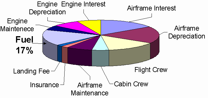
Figure 1 Breakdown of Direct Operating Costs (DOC)
Figure 1 shows a typical breakdown of the costs of operation of a long range large civil aircraft. It shows that the cost of the engine and of the fuel amount to similar proportions and that together, they account for some 38 percent of the total cost. One percent of operating costs is equivalent to approximately $200,000 per aircraft per year. To achieve a reduction of just one percent requires, approximately, a 1 percent increase in LP turbine efficiency, an 8 percent reduction in engine cost or a 17 percent reduction in engine weight. The LP turbine is the largest single component in the engine. Consequently, reductions in component number and weight have a direct impact on the cost of the engine. The LP turbine is also the most efficient component of the engine.
To date, reductions in cost and weight have been achieved through the reduction in the number of airfoils in a given bladerow (high lift and ultra high-lift blading) whilst maintaining efficiency. Studies suggest that with pitch-chord ratios now much greater than unity, further increases in lift are unlikely to be beneficial. Nevertheless, further reductions in cost and weight are now sought. These must be achieved by re-applying the ultra high-lift technology that has been developed at the Whittle Laboratory in conjunction with Rolls-Royce, Rolls-Royce Deutschland and ITP, to design LP turbines with increased stage loading. These designs must also operate at lower levels of noise emission and at higher efficiency. Increases in stage loading are also required because new constraints on fuel efficiency, emissions and noise are likely to require fans with larger diameters operating at lower rotational speeds.
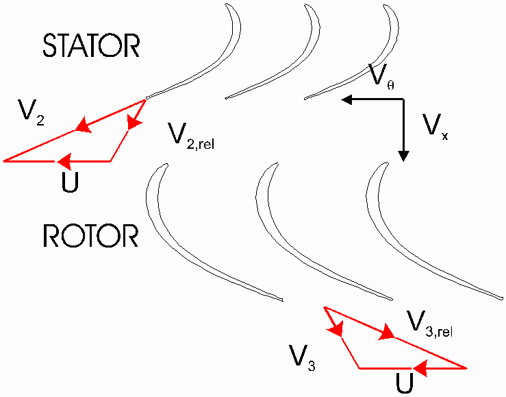
Figure 2 Typical "Thin-Solid" Low Weight LP Turbine
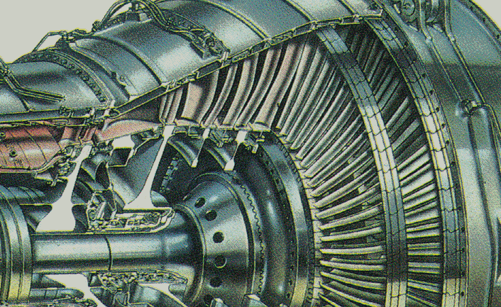
Figure 3 Rolls-Royce Trent 800 LP Turbine
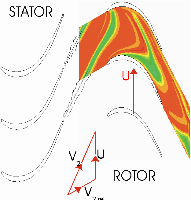
Figure 4 Calculation of wake-blade interaction in an LP turbine
Figure 2 and Figure 3 show typical LP turbine geometries. The LP turbine comprises approximately 1/3rd of the engine’s weight. There are typically 5 stages, with about 900 airfoils. Each airfoil has a large span and so two dimensional flow is prevalent. Also, the Mach numbers rarely exceed unity and are typically 0.6 to 0.8 at exit from each bladerow. It is for these reasons that blade-to-blade based flow field studies have been so successful in leading to the improvements in the LP turbine described above. Set against these facts, the chord-based Reynolds numbers lie typically in the range 1.2 to 4.5x10⁵ which means that the boundary layer flows are often transitional. Until the development of the high lift blading, conventional wisdom held that the transitional behaviour of the boundary layers would limit the blade loading. In fact, the high lift concept uses the wakes from upstream bladerows to manage the transition process on downstream airfoils. In so doing, the lift has been increased by 40 percent above the original baseline.
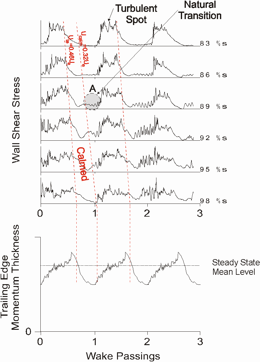
Figure 5 Wake-induced transition on high lift LP turbine blade: surface shear stresses measured using surface mounted hot film anemometers and trailing edge momentum thickness measured using a hot wire anemometer.
Figure 4 shows an example of a series of wakes passing through a downstream bladerow. At about mid-chord, the turbulence within the wakes promotes transition in the boundary layers on the suction side. Figure 5 presents data obtained in a the low speed cascade (see Figure 6) at the Whittle Laboratory. The upper part of the figure shows how the wall shear stress varies in time with the passing of wakes at successive points on the suction surface. Only the last part of the suction surface is shown. The data reveal that the wakes cause transition and that a turbulent (high) wall shear stress results. After this event has passed, the flow relaxes back to the steady state. This relaxation period occupies the so-called "calmed zone". The calmed zone a relatively full velocity profile that can withstand large adverse pressure gradients without separating. In the absence of the wakes, the flow would separate are the loss of efficiency would be large. Therefore, higher lifts are possible.
The calmed zone is essentially laminar in nature and so very little entropy produced. Under the right circumstances the reduced entropy production within the calmed period outweighs penalty of the increased entropy production in the turbulent flow caused by wakes. The lower plot in Figure 5 shows how the trailing edge momentum thickness (effectively loss of efficiency) varies during the same wake-passing events. The increased loss during the turbulent period and the reduced loss in the calmed period are clearly visible. Overall, there is a net reduction in loss at higher lifts when compared to the steady state low lift datum. This has also been verified using efficiency measurements and surface mounted hot film anemometers (see Figure 7) in the BR715 LP turbine.

Figure 6 Large Scale Low Speed Moving Bar Rig
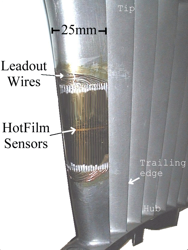
Figure 7 BR715 LP Turbine Surface mounted hot film anemometry
The proposed research will focus on the use of High Lift blading in LP turbines with higher stage loadings. The overall objectives are to produce these turbines at a lower cost with a lower weight and with an increased efficiency. Unfortunately, higher stage loadings imply a higher turning and lower velocity ratios across each bladerow. This, in turn, challenges the suction surface design. To date, the improvements in LP turbines have resulted mainly from the careful design of the suction side velocity distributions to ensure that the benefits of the unsteady flow are maximised. The importance of this aspect of design will continue.
Unfortunately, the use of higher loadings also leads to higher leading edge loadings. These inevitably lead to problems caused by velocity overspeeds at the leading edge. To date, these have been avoided but there are two known consequences. The first is the development of significant pressure side separation bubbles. These may extend from the leading edge to beyond mid chord. The second arises due to the interaction of the separation bubble and the endwall or "secondary" flow. The strength of the secondary flows is already increased as a result of the increased blade loading. However, the strong adverse pressure gradient near the endwall-pressure surface corner of the thin airfoils can lead to further increases in the strength of the secondary flows and a consequent reduction in efficiency. Both of these phenomena are visible in the CFD prediction shown in Figure 8.
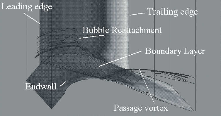
Figure 8 Streamlines passing through the separation and into the secondary flow
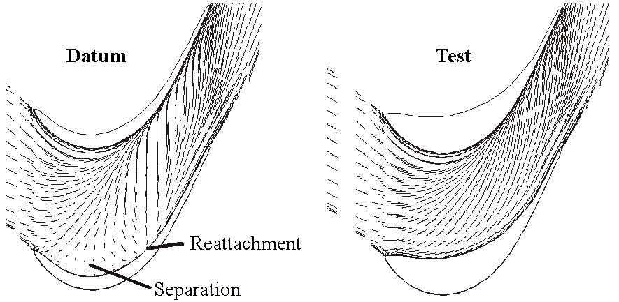
Figure 9 Endwall streamlines for datum and test profile
The interaction between the pressure surface separation and the secondary flow has been studied in a steady inflow linear cascade using a datum thin, solid profile and varying the shape of its pressure surface near the endwalls. This is known as "spooning" or "endwall tapering". Figure 9 shows how the predicted endwall streamlines are affected by this change in the design. When the separation becomes smaller or is removed completely, less fluid from the separation is entrained into the secondary flow, the secondary flow becomes weaker and the efficiency rises. Unfortunately, the use of tapered airfoils adds weight and cost to the engine. Ways must therefore be found to minimise these costs.
THE RESEARCH OBJECTIVES
The objectives of this research project are to develop a thorough understanding of the physical phenomena associated with the flows in LP turbines and to use that understanding to develop improved designs. The program is based on theoretical and experimental research. The experiments will involve rigs tests such as in the unsteady low speed cascades and high speed cascade at the Whittle Laboratory and the cold flow turbine rigs which will run at the CTA facilities in Spain. They will also involve more fundamental studies. In-house codes (3-D steady and unsteady, structured and unstructured, Navier-Stokes) will be used to assess the experimental data, to direct the research, to expand the experimental data base and to produce new designs.
The research will focus on the use of High Lift blading in LP turbines with higher stage loadings. In particular, it will be concerned with reducing the losses associated with secondary flows by almost 50 percent. Several approaches will be utilised in order to achieve this reduction, for example, using
THE WHITTLE LABORATORY
The research will be carried out at the Whittle Laboratory, Cambridge University Engineering Department. The Whittle Laboratory was established in 1971 and has played a leading role in the field of Turbomachinery. The Laboratory specialises in research into the fluid dynamics and thermodynamics of all types of turbomachinery. The laboratory has excellent contacts with industry and other research organisations. Much of the research is supported by contracts from industries and governments from around the world. The work in the Laboratory is equally divided between the numerical prediction of the flow through turbomachines and the experimental research using a wide variety of facilities. The Laboratory has first class computational and experimental facilities and offers many unique opportunities for high quality research.
The University aims to achieve the highest quality in teaching and research.
PhD RESEARCH STUDENTSHIP
The successful applicant will be responsible for the research described above under the supervision of Dr. Howard Hodson. The proposed research encompasses the fields of unsteady aerodynamics, laminar-turbulent transition, and 3D flows in the context of high blade loading and high stage loading. The research student will be part of a team working in this important area of research. The successful applicant will be expected to conduct important experiments and will also responsible for the computational studies in support of this work.
The studentship will be for three years, with a starting date of 1st August 2000 or as soon as possible thereafter. A minimum annual maintenance grant (currently £6,455 p.a.) is offered. Depending upon the applicant's circumstances, a further award up to the value of a CASE award (currently £3000 p.a.) may be available. The fees for registration as a PhD student and for membership of a Cambridge college are also covered. The candidate will be expected to register for a Ph.D. It is envisaged that the successful candidate will have a First Class Honours or Masters degree in Mechanical or Aeronautical Engineering.
Further details and application forms may be obtained from Dr. H.P. Hodson (hph@eng.cam.ac.uk), Whittle Laboratory, Madingley Road, Cambridge CB3 ODY. Completed application forms and a current curriculum vitae, including the names and addresses of two referees should be sent to the above not later than 20th April 2000.