A TRIBUTE TO A CAMBRIDGE ENGINEERING
STUDENT (PETERHOUSE 1934 - 1936) WHO
HAS ACHIEVED WORLD FAME
Sir Frank Whittle OM KBE CB FRS
1907 - 1996
|
A TRIBUTE TO A CAMBRIDGE ENGINEERING Sir Frank Whittle OM KBE CB FRS 1907 - 1996
|
|
DR. HENRY COHEN* AND KENNETH KNELL** FIRST COMPILED THIS EXHIBIT IN 1963. SINCE THEN IT HAS BEEN DISPLAYED REGULARLY IN THE ENGINEERING DEPARTMENT AND SEEN BY MANY GENERATIONS OF UNDERGRADUATES. THIS ABRIDGED VERSION WAS PRESENTED AT THE TIME OF WHITTLE'S DEATH, 8 AUGUST 1996, AS A LASTING REMINDER OF HIS PIONEERING WORK ON THE TURBO JET ENGINE.
|
1. BIBLIOGRAPHICAL & REFERENCES
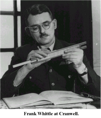
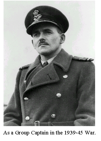
Sir Frank Whittle was a native of Coventry. He joined the Royal Air Force as an apprentice in 1923 and in 1926 was awarded a cadetship at the R.A.F. College, Cranwell, whence he graduated as a Pilot Officer in 1928. After eighteen months as a pilot in No.111 Fighter Squadron he spent 1930 instructing at No.2 F.T.S. Digby as a Flying Officer. In the same year he also applied for his first turbo-jet engine patent. In 1931 and 1932 he was a floatplane and catapult test pilot at the Marine Aircraft Experimental Establishment, Felixstowe. In 1934 he completed the Officers' Engineering Course and, as a Flight Lieutenant, he attended Cambridge University, until 1936, where he received his B.A. with first class honours in the Mechanical Sciences Tripos. He did post-graduate work there and worked on designing his engine until, in 1937, he was posted to the Special Duty List to continue jet engine development and was promoted to Squadron Leader. He remained on the Special Duty List until 1946, except for attending the War Staff College Course, and was successively promoted to Wing Commander, Group Captain and Air Commodore. In 1946 he was appointed Technical Adviser to the Ministry of Supply and Aircraft Production. He retired from the Royal Air Force in 1948, owing to ill health. From 1948-1952 he was Hon. Technical Adviser to the British Overseas Airways Corporation, and from 1953-1957 was Mechanical Engineering Specialist to B.P.M. Sir Frank Whittle received the C.B.E. in 1944; the C.B. in 1947 and his K.B.E. in 1948 and was also made a Commander of the U.S. Legion of Merit. He was elected a Fellow of the Royal Society in 1947 and was awarded several honorary degrees, and many medals, including the Rumford Medal, the Daniel Guggenheim Medal and the Franklin Medal. He settled in America in 1976 and was a member of the Naval Academy, Annapolis, Maryland. He was awarded the Order of Merit in 1986, and jointly with Dr H P von Ohain, he was awarded the Charles Stark Draper Prize in 1992. He had two sons by his first marriage. He died on 8th August 1996.
|
|
As a Group Captain in the 1939-45 War. | 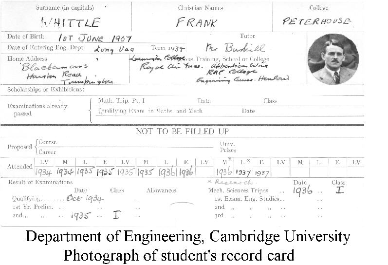 |
DEPARTMENT OF
ENGINEERING Photograph of student's record card. |
 |
TRIPOS GROUP 1936 Frank Whittle,seated, centre second row from front. |
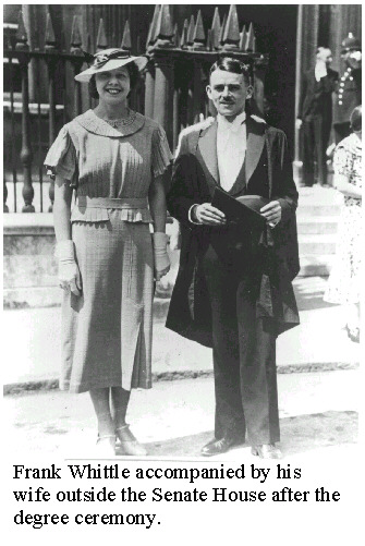 |
Frank Whittle accompanied by his wife outside the Senate House after the degree ceremony. |
 |
Frontispiece from the book 'JET' by Sir Frank Whittle. (Reference 2) |
|
Frank Whittle at Brownsover Hall, Lutterworth. |
References
(1) Whittle's James Clayton lecture as published in Proc. I. Mech. E., 152, pp 419-435 (1945). (Selections from this form the first part of the exhibition.)
(2) Jet, by Sir Frank Whittle. 1953. Frederick Muller.
(3) Aircraft Engines of the World, by P. H. Wilkinson. 1946 – 63. Pitman.
(4) Jet Propulsion Engines, ed. by O. E. Lancaster. 1959. OUP.
(5) Aviation: its technical development, by J. L. Nayler and E. Owen. 1965. Peter Owen – Vision Press.
(6) Whittle: the True Story, by J. Golley. 1987. Airlife Publ. Co.
(7) Booklet (no title) by Derek N. James, 1979
(8) Jet Pioneer by Don Middleton. Fly Past, page 17 (November, 1990)
(9) Genesis of the Jet, by John Golley
See also Section 17 for obituaries and other references.
2. BIRTH OF AN IDEA
DEVELOPMENT OF THE ENGINE
The diagrams and photographs show, in chronological order, important steps in the development.
The accompanying comments are extracted from Sir Frank's paper to the Institution of Mechanical Engineers. It is the First James Clayton Lecture entitled: "The early history of the Whittle jet propulsion gas turbine", and can be read in full in Vol. 152 (1945) of the Proceedings (Reference (1)). It is reproduced here by courtesy of the Council of the Institution of Mechanical Engineers. (The material relating to the Royal Aircraft Establishment (Crown Copyright) is reproduced with the permission of the Controller of Her Majesty's Stationery Office.)
There have been many attempts to solve the gas turbine problem in the past but at the time I started thinking about the subject, i.e. in 1928-9, the many failures had led to a general belief in the engineering world that it had no future.
I first started thinking about this general subject in 1928, in my fourth term as a Flight Cadet at the RAF College, Cranwell. Each term we had to write a science thesis, and in my fourth term I chose for my subject the future developments of aircraft. Amongst other things, I discussed the possibilities of jet propulsion and of gas turbines; but it was not until eighteen months later, when on an Instructors' course at the Central Flying School, Wittering, that I conceived the idea of using a gas turbine for jet propulsion. I applied for my first patent in January 1930.
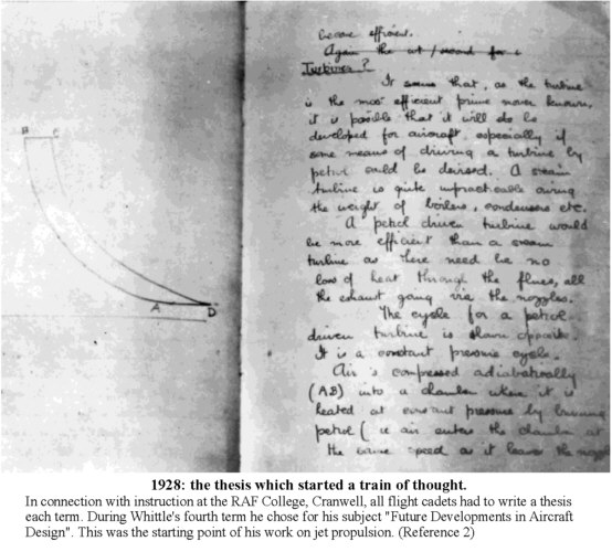 |
1928: The Thesis which started a train of thought. (Reference 2) | 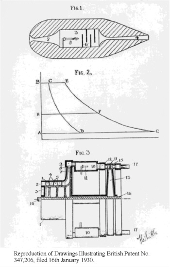 |
Reproduction of Drawings Illustrating British Patent No. 347,206, filed 16th January 1930. |
3. FIRST MODEL EXPERIMENTAL ENGINE
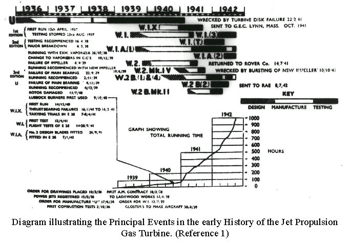 |
Diagram illustrating the Principal Events in the early History of the Jet Propulsion Gas Turbine. (Reference 1) |
Nothing very much happened for a few years. I gave up hope of ever getting the idea to the practical stage, but continued to do paper work at intervals, until, in May 1935, when I was at Cambridge as an Engineer Officer taking the Tripos Course, I was approached by two ex-RAF officers (Mr. R.D. Williams and Mr. J.C.B. Tinling), who suggested that they should try to get something started. Though I had allowed the original patent to lapse through failure to pay the renewal fee, and though I regarded them as extremely optimistic, I agreed to co-operate. I thought that there was just a bare chance that something might come of it ....
The engine was to be a simple jet propulsion gas turbine having a single-stage centrifugal compressor with bilateral intakes, driven by a single-stage turbine directly coupled. Combustion was to take place in a single combustion chamber through which the working fluid passed from the compressor to the turbine.
We were going beyond all previous engineering experience in each of the major organs. We were aiming at a pressure ratio of about 4 : 1 in a single-stage centrifugal blower when at the time, so far as we knew, a ratio of 2 1/2 : l had not been exceeded. We were aiming at a breathing capacity in proportion to size substantially greater than had previously been attempted. The combustion intensity we aimed to achieve was far beyond anything previously attempted. Finally, we had to get over 3,000 s.h.p. out of a single-stage turbine wheel of about 16 1/2 inches outside diameter, and to do it with high efficiency.
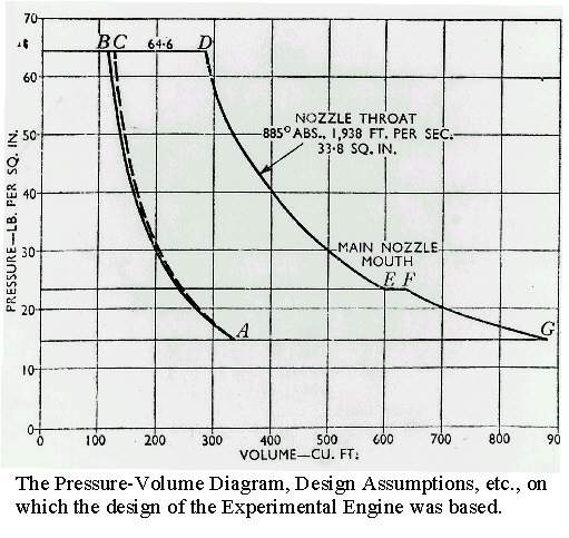 |
The Pressure-Volume Diagram, Design Assumptions, etc., on which the design of the Experimental Engine was based. | 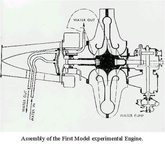 |
Assembly of the First Model experimental Engine. |
This first engine was based on a design for flight, but was not intended for flight; and though it was designed to be very light by normal engineering standards, we did not put forth special efforts to make it as light as possible.
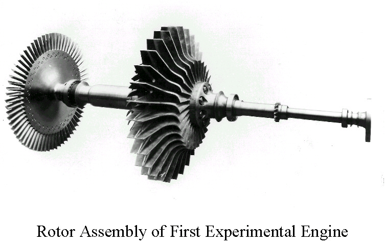 |
Rotor Assembly of First Experimental Engine. |
While the engine was in course of design and manufacture, we carried out a number of combustion experiments on the premises of the British Thomson-Houston Company, with apparatus supplied by Laidlaw, Drew and Company, until we considered that we had enough information to design a combustion chamber.
By this time the Tripos Examinations at Cambridge were over, and the Air Ministry had agreed that I should stay for a post-graduate year. This was really a device to enable me to continue work on the engine, and so a considerable proportion of my time was spent at the British Thomson-Houston Company's works in Rugby.
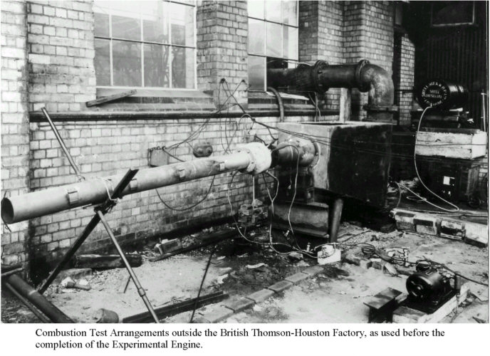 |
Combustion Test Arrangements outside the British Thomson-Houston Factory. | 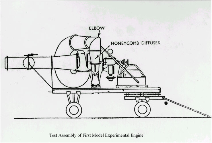 |
Test Assembly of First Model Experimental Engine. |
Testing of the engine commenced on 12th April 1937, and continued intermittently until 23rd August. These early tests made it clear that the combustion problem was by no means solved, and the compressor performance was far below expectations. Nevertheless, they were sufficiently encouraging to show that we were on the right track
 |
Test Assembly of First Model Experimental engine. |
4. SECOND MODEL EXPERIMENTAL ENGINE
We succeeded in reaching a speed of 13,600 rpm, then it was decided to make major modifications to the general arrangement. The main aims of the reconstruction were to obtain a single straight combustion chamber and to provide a much-improved diffuser system for the blower. In particular, complete symmetry about the axis was aimed at.
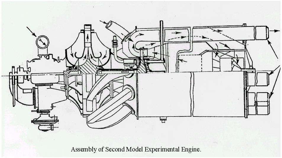 |
Assembly of Second Model Experimental Engine. | 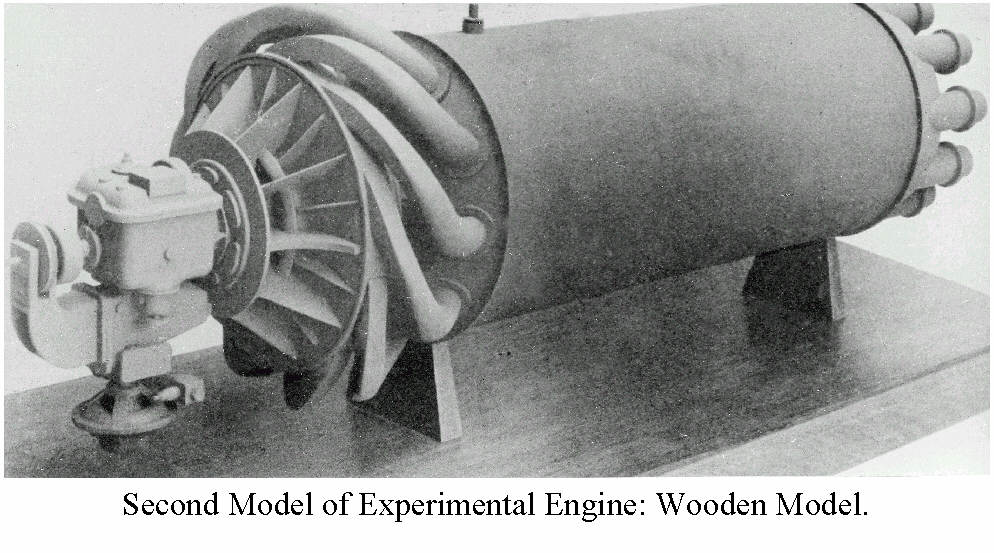 |
Second Model of Experimental Engine: Wooden Model. |
5. THIRD MODEL EXPERIMENTAL ENGINE
Only nine Test runs were made on the second model of the experimental engine, because the ninth test was brought to an end by a turbine failure which caused fairly extensive damage.
For eight of these test runs the speed never exceeded about 8,500 r.p.m., but in the last run of the series a speed of 13,000 r.p.m. was maintained for half an hour, at the end of which the failure occurred.
Another major change in the arrangement of the engine was decided upon. This was in many ways a compromise between the two arrangements already tried. The main feature was the use of multiple combustion chambers.
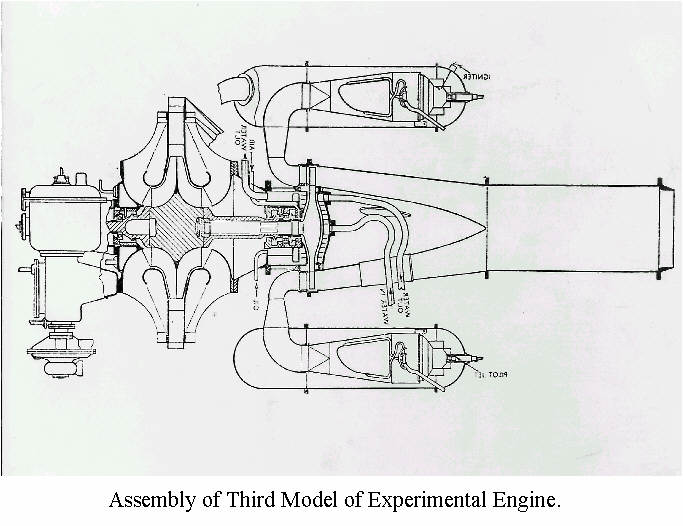 |
Assembly of Third Model of Experimental Engine. | 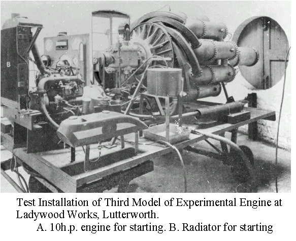 |
Test Installation of Third Model of Experimental Engine. |
Testing began at the end of October 1938 and continued with increasing intensity until the engine was wrecked by the failure of the turbine disk in February 1941.
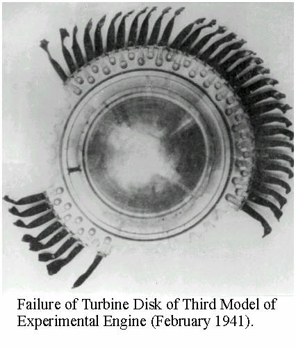 |
Failure of Turbine Disk of Third Model of Experimental Engine (February 1941). |
The development of the series of Whittle engines proved there were many difficulties to be overcome. These included surging, high jetpipe temperatures and turbine blade failure. The latter was overcome due to the improvement in turbine blade material as developed by Mond Nickel of the high nickel alloy called Nimonic 80 (Reference 6).
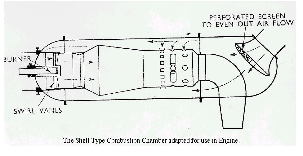 |
The Shell Type Combustion Chamber adapted for use in Engine. |
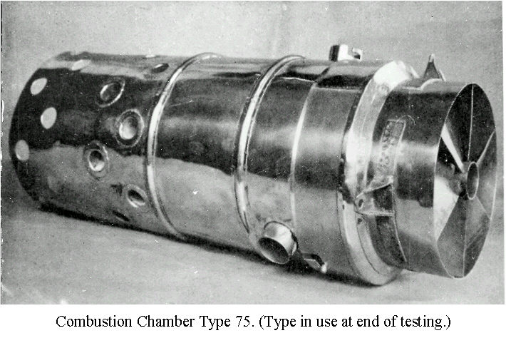
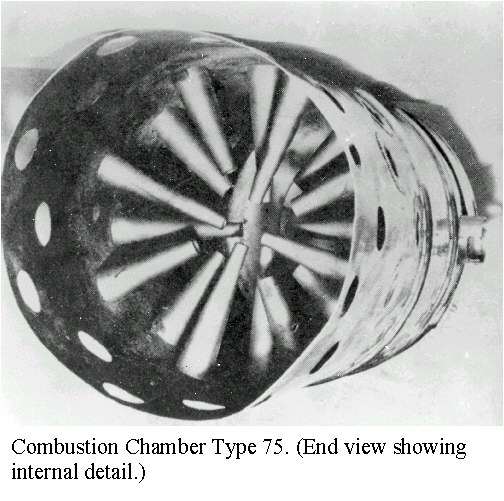
Practically the whole of the testing was dominated by the combustion problem. For two years we struggled with a combustion system based upon the pre-vaporization of the fuel, but eventually had to abandon it. I cannot possibly give an adequate picture of that heartbreaking period. The "Shell" combustion chamber was the starting point of a new phase in the development. Power Jets now commenced intensive development both on the controllable atomizing burner and on the other features of the "Shell" combustion chamber.
|
|
|
Combustion Chamber
Type 75. RIGHT: View of secondary-air injection system showing conical nozzles. |
6. FIRST FLIGHT ENGINE - W1 AND GLOSTER AIRCRAFT E28/39
After certain preliminary testing, the W1 was put through a 25-hours special category test to clear it for flight.
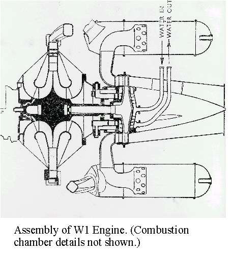 |
Assembly of W1 Engine. | 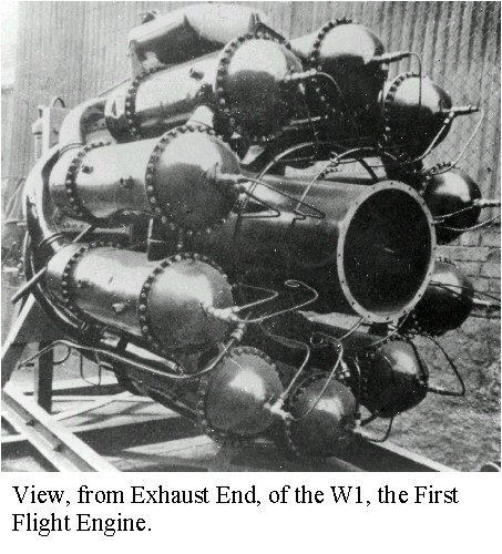 |
View from Exhaust End of the W1, the First Flight Engine. |
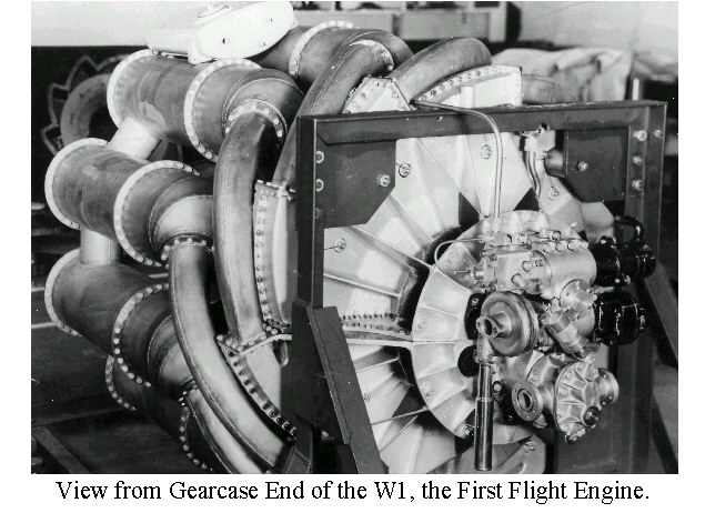 |
View from Gearcase End of the W1, the First Flight Engine. | 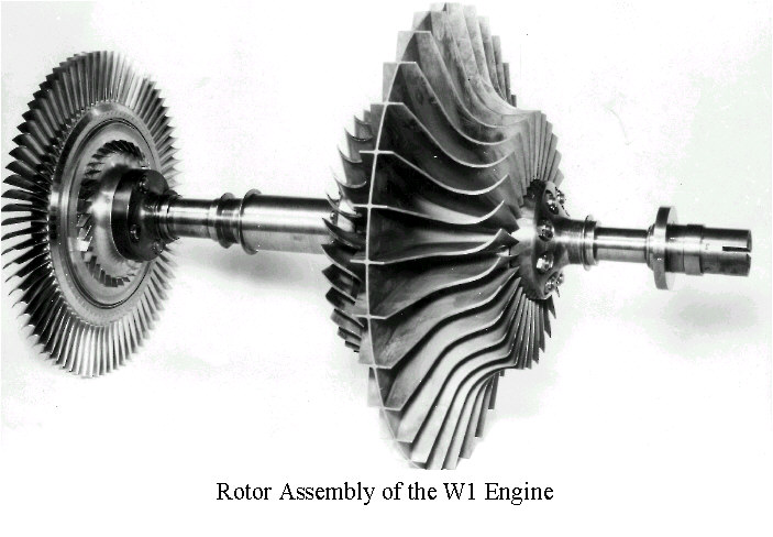 |
Rotor Assembly of the W1 Engine. |
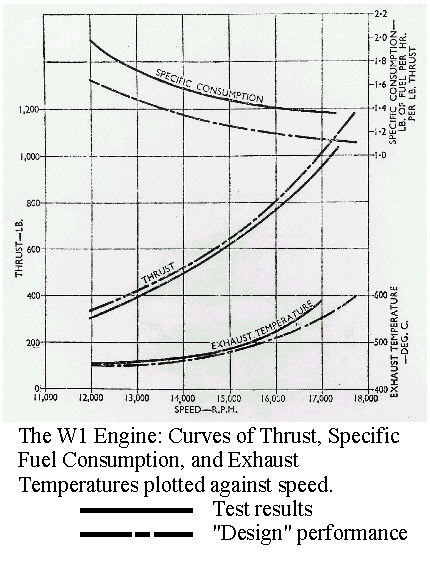 |
The W1 Engine: Curves of Thrust, Specific Fuel Consumption, and Exhaust Temperatures plotted against speed. |
THE GLOSTER E28/39
The Gloster E28/39 aircraft was designed especially to flight test Whittle's W1 jet engine. It is a remarkable aircraft by any standard. Two examples were built (W4041 and W4046) under the design leadership of George Carter, chief of Gloster's design office.
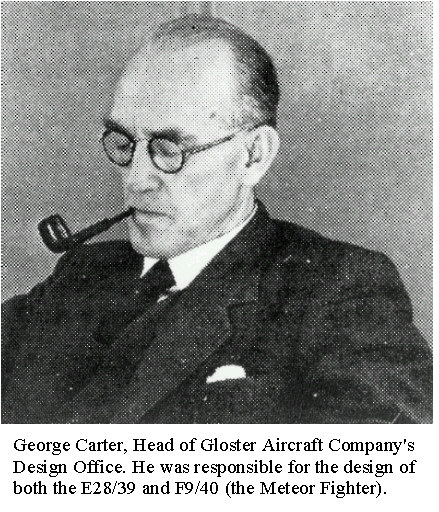 |
George Carter, Head of Gloster Aircraft Company's Design Office. He was responsible for the design of both the E28/39 and F9/40 (the Meteor Fighter). |
After seeing the W1 engine running on the test bed at Lutterworth, and learning from Whittle the estimated thrust of the engine, the E28/39 was conceived and built within 15 months.
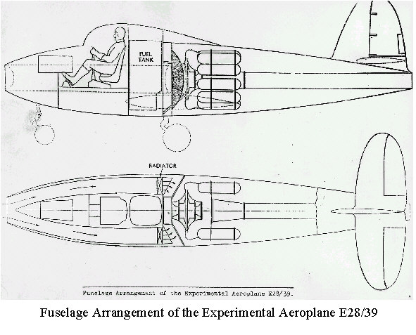 |
Fuselage Arrangement of the Experimental Aeroplane E28/39 | 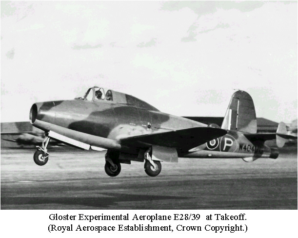 |
Gloster Experimental Aeroplane E28/39 at Take-off. (RAE Crown Copyright.) |
W4041, piloted by Gerry Sayer, took off from Cranwell at 7.45 p.m. on 15th May 1941. This historic flight had a duration of 17 minutes.
The second aircraft, W4046, first flew on 1st March 1943. It was demonstrated to Winston Churchill on 17th April 1943. Three months later this aircraft crashed after experiencing jammed ailerons and an inverted spin at 33,000 feet. (The RAF pilot baled out.)
W4041 was later transferred to RAE Farnborough where numerous test programmes were successfully carried out. It can now be seen in the Science Museum, South Kensington, where it has been on display since 1946.
(Information from a booklet written by Derek N. James, which was produced for the unveiling of a memorial to the E28/39 on 23rd May 1979.) (Reference 7)
It is not generally appreciated what an outstanding aircraft the Gloster E28/39 was, and how brilliantly W.G. Carter and his team solved the problems presented by this entirely new type. Although specified for a maximum speed of 450 mph it exceeded that figure by more than 50 mph.
TEST PILOT'S RECORD OF FIRST FLIGHT
The first flight of the Gloster E28/39 with the Whittle W1 turbo-jet engine took place secretly at Cranwell on 15th May 1941. It lasted 17 minutes. On landing the test pilot, Flight-Lieutenant P.E.G. (Gerry) Sayer, standing next to the aircraft, made this fair copy of the notes he had scribbled on his knee-pad during the flight.
NOTE: This copy of the notes was supplied by Sir William Hawthorne F.R.S., Professor of Thermodynamics, Head of the Engineering Department (1968-73) and Master of Churchill College. Sir William, as a young engineer, was sent on loan from the Royal Aircraft Establishment to lead a group on combustion at Whittle's Power Jets Company. He later became Head of the Gas Turbine Division at RAE before taking up his academic appointment at Cambridge.
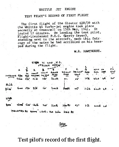 |
Test pilot's record of the first flight. |
The whole project received a powerful stimulus from the successful flight trials of the E28. The Ministry of Aircraft Production decided to plan for production of the W2B and the Meteor. Many sceptics were converted. The firms already engaged increased their activities considerably, and other firms, which had practically ignored the gas turbine, suddenly evinced a lively interest.
7. W1A ENGINE
The "W1A" was an engine incorporating most of the features of the W1 but it also had in it certain of the special features of the W2 it was desired to test in advance.
The general arrangement, as may be seen, has many features in common with the W1, but air cooling was used for the turbine instead of water cooling, the fins of the air cooling fan being machined integral with the turbine disk.
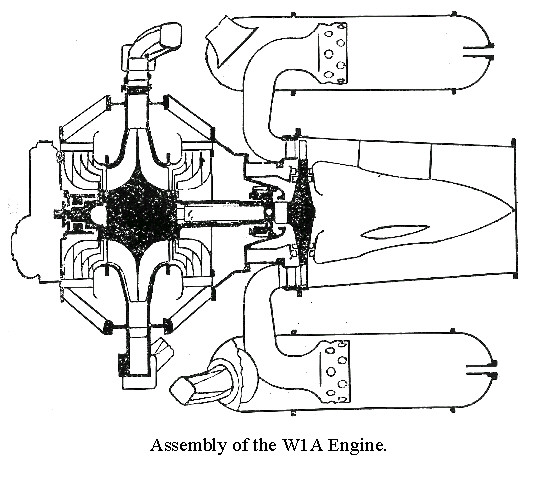 |
Assembly of the W1A Engine. | 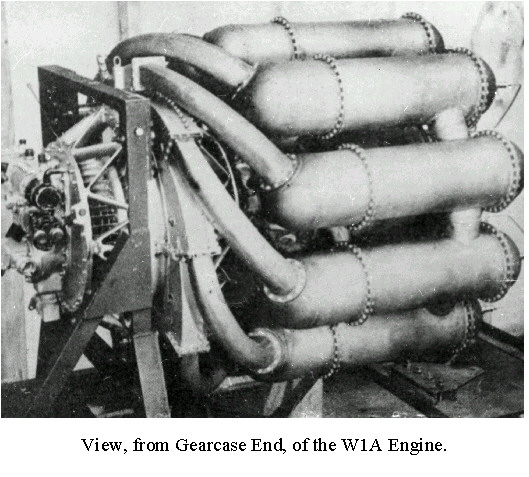 |
View, from Gearcase End, of the W1A Engine. |
8. W2B ENGINE (ROLLS-ROYCE WELLAND)
The "W2B" was originally designed by Power Jets, and complete sets of Power Jets' drawings were passed to the several firms by then engaged. The first and second W2Bs to be tested by Power Jets were manufactured by the Rover Company, and (like the W2) differed from the Power Jets' design in certain mechanical features.
The W2B was the prototype of the Welland engines (which subsequently powered Meteor I in this country) and of the "Type I" (the corresponding engine made by the American General Electric Company which powered the Bell Airacomet, and which was the fore-runner of a series of similar engines made by the American General Electric Company).
(Material for the Exhibition up to this point is taken from Reference 1 unless otherwise stated.)
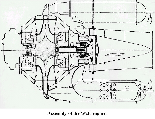 |
Assembly of the W2B engine. | 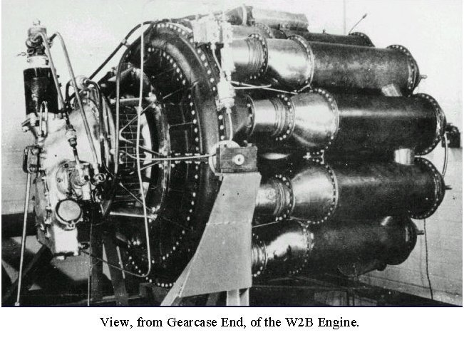 |
View, from Gearcase End, of the W2B Engine. |
9. W1X AND THE BELL AIRCRAFT AIRACOMET XP-59A
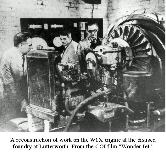 |
A reconstruction of work on the W1X engine at the disused foundry at Lutterworth. From the COI film "Wonder Jet". |
An engine designated theW1X, which was made up of various spare components, was put together to achieve an additional non-flying engine (November 1940).
On October 1st 1941 the W1X, disassembled to packing-case size, accompanied by a Power Jets team comprising Dan Walker, Flight Sergeant King and G.B. Buzzoni, was flown to Bolling Field, Washington, in the bomb bay of a Liberator… They were worried all the time that the pilot might pull the wrong toggle and deposit them into the drink...
The W1X gave the American aircraft industry a free passport into the field of aero gas turbines. This happened before America had entered the War and Britain was fighting alone and in desperate need of lend-lease arms. The Whittle engine was to turn out to be more than a quid pro quo. In addition, shortly after the end of the war, the Rolls-Royce version was given to the USSR!
The Americans wasted no time in tackling this jet project, which NACA (National Advisory Committee on Aeronautics) judged of vital national importance. In August 1941 (3 months after the flight of the Gloster E28/39) General Electric received a contract to build 15 Whittle engines, designated I-A. Bell Aircraft of Buffalo was selected to build three aircraft; the XP-59A Airacomet made its maiden flight (October 1942) some six months before the Meteor became airborne. It achieved a top speed of 380 m.p.h. (Reference 6)
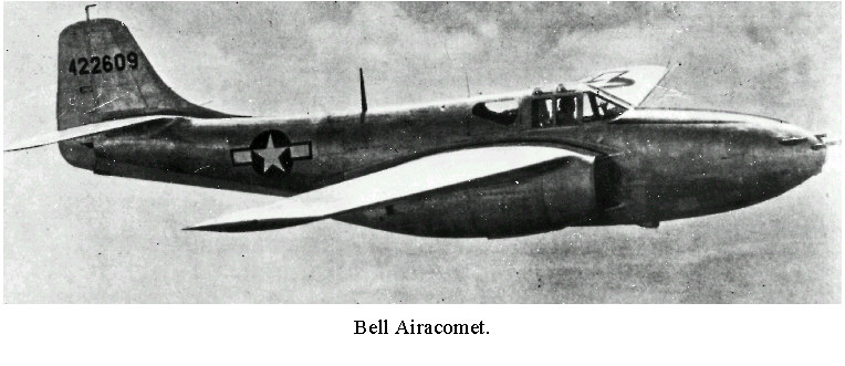 |
Bell Airacomet. |
10. GLOSTER METEOR FIGHTER AIRCRAFT
THE ALLIES' ONLY OPERATIONAL JET AIRCRAFT IN WORLD WAR II
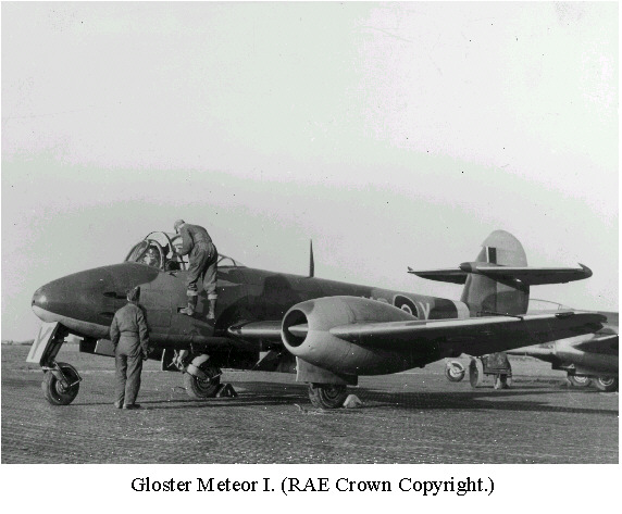 |
Gloster Meteor I. (RAE Crown Copyright.) |
In February 1941 the Gloster Aircraft Company received an order for 12 "Gloster Whittle" aeroplanes. Long before the E28/39 was conceived, George Carter (Gloster's chief designer) had been planning a twin engined fighter, so the design office team was well placed to design an aircraft to accept two jet engines. This became known as the Meteor.
Test pilot Michael Daunt flew the prototype on 5th March 1943 from Cranwell. There were several bugs to be eliminated before the Meteor became the successful aircraft that it was. These prompted Michael Daunt to compose this poem to George Carter:-
"Sing a song of shock stall Words by Ernest Mach, Four and twenty slide rules Are shuffling in the dark. Begone oh doubting fancies Our George will fit the bill, But George, please make the Meteor A wee bit meatier still." |
When in service (July 1944), the RAF Meteor squadrons were mostly used to counter the threat from the 7,000 V1 flying bombs aimed at this country. The Meteors (achieving a top speed of 480 m.p.h.) were fast enough to fly alongside the V1s and to 'knock' them out of the sky by using the Meteor's wing tip to flip them on their backs.
In total 3,875 Meteors were built in Britain, Holland and Belgium between 1943 and 1954.
(Information from the booklet by Derek N. James, 1979 (Reference 7) and the magazine 'Fly Past', November 1990, article by Don Middleton, 'Jet pioneer', page 17 (Reference 8).)
ENGINES FITTED TO THE EIGHT PROTOTYPE GLOSTER F9/40 (METEORS):
CENTRIFUGAL TURBOJETS:
De HAVILLAND H.1 (HALFORD)
POWER JETS W1
ROVER W2
ROLLS-ROYCE W2B (WELLAND)
AXIAL TURBOJET:
METROPOLITAN VICKERS F2
11. PROGRESS IN JET PROPULSION
CENTRIFUGAL-FLOW ENGINE – REVERSE-FLOW TYPE
(Professor N.A. Cumpsty, Head of the Whittle Laboratory until 1999, points out that the
centrifugal compressor was used because of the known difficulty of making an axial
compressor. With a centrifugal compressor use could be made of the knowledge of pumps and,
unlike the axial compressor, substantial pressure rise could be produced no matter how bad
the aerodynamic design. By directing the air flow radially outwards the centrifugal
compressor generally complicates the layout of the engine and creates a larger frontal
area; this becomes a more serious problem as the flight speeds approach the speed of
sound.)
The company formed by Whittle, known as Power Jets Ltd, produced the W2B engine which was a classic of its type. It had the reverse flow combustion system, which was typical of the Whittle designs. It was eventually developed to give nearly three times the thrust of the W1 without occupying more space.
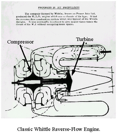 |
Classic Whittle Reverse-Flow Engine. | 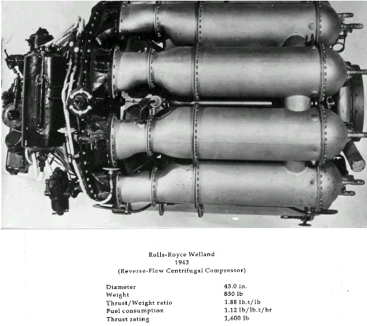 |
Rolls-Royce Welland 1943. Thrust rating 1,600 lb |
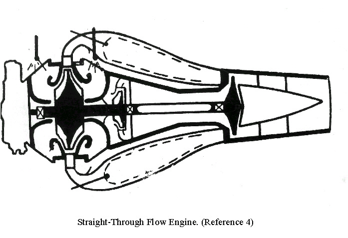
CENTRIFUGAL-FLOW ENGINE – STRAIGHT-THROUGH-FLOW TYPE
When other firms were drawn into jet engine production the first to be so engaged was the Rover Company in the Spring of 1940. Rover finally passed their work over to Rolls-Royce in 1943, but not before they had pioneered a change in design from the reverse flow combustion chamber to the straight-through type. Their prototype engine, the W2B26 ran in March 1942, and served as a direct basis for the Derwent I, which was later developed by Rolls-Royce.
|
|
Straight-Through Flow Engine. (Reference 4) |
|
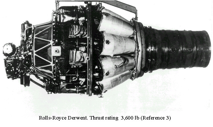
Rolls-Royce Derwent. Thrust rating 3,600 lb (Reference 3) |
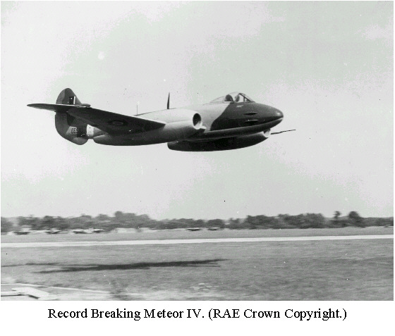 |
Record Breaking Meteor III with Derwent engines. (RAE Crown Copyright.) |
Thanks to the enormous improvements made to the jet engine a Gloster Meteor IV, basically the same as the standard R.A.F. fighter, was able to aim at increasing the world's speed record to over 600 m.p.h. for the first time.
For structural and control reasons the thrust of the two Rolls-Royce Derwent Vs was limited to 3,600 lbs (at least 400 lbs of thrust being withheld). Note the length of the power nacelles to deal with certain compressibility effects.
The photograph shows a Meteor III of the type used to increase the record to 616 m.p.h. on 7th September 1946.
Another company early in the field was de Havilland. In January 1941, with the aid of Halford, work commenced on the "Goblin". The Halford engine was born from the PJ designs given to the Havillands. This was followed by the "Ghost", four of which powered the DH Comet 1 series, maiden flight, July 1949.
12. HISTORICAL NOTE: CENTRIFUGAL-FLOW v. AXIAL-FLOW COMPRESSORS
The compressor is an essential component of the turbojet engine. It has developed along two main lines:
(1) Centrifugal-flow
(2) Axial-flow
During the 1930s different engineers were developing engines of both types.
 |
Sir Frank Whittle and Pabst (Hans) von Ohain at a meeting arranged by General Electric. They became good friends. (Reference 6) |
Centrifugal-flow Compressors
This was the type of compressor used by Hans von Ohain and Frank Whittle.
Von Ohain's HeW 3B engine installed in the Heinkel He178 made the world's first turbojet flight on 27th August 1939. The aircraft was flown by test pilot Warsitz.
Whittle's W1 engine installed in the Gloster E28/39 first flew 15th May 1941, piloted by P.E.G. (Gerry) Sayer.
Development of the von Ohain type engine was abandoned in 1941. Whittle's engine was further developed: Power Jets designed the W2B which, initially manufactured by the Rover Company and then by Rolls Royce, became the Welland in 1943. This powered the Gloucester Meteor 1, which flew on 5th March 1943. The Meteor 1 became operational in July 1944.
|
|
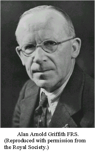
Alan Arnold Griffith FRS. (Reproduced with permission from The Royal Society.) |
|
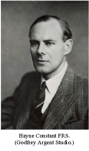
Hayne Constant FRS. (Godfrey Argent Studio.) |
Axial-flow Compressors
The first British engine to use an axial-flow compressor was the RAE/Metrovick F2, which ran on its test bed in 1940. It was the work of A.A. Griffith and Hayne Constant, both of the Royal Aircraft Establishment. A pair of these engines was experimentally fitted to a Meteor in 1943; they were not put into production.
The Germans concentrated on the Junkers Jumo 004B axial-flow engine for the aerodynamically-advanced Messerschmitt ME262-A, which made its maiden flight on 18th July 1942. It became operational in October 1944.
The Jumo 004B was closer to the style of modern jet engines, but its reliability was not as good as the Welland; it was heavier and used more fuel. The Whittle engine proved to be remarkably trouble-free.
NOTE: Professor N.A. Cumpsty also reminds us of a little known fact; namely, that the Japanese also flew a jet engine in 1945, which although owing much to German technology, was designed by themselves.
Conclusion
Rolls Royce continued their range of centrifugal-flow types, including Derwent (1943), Nene (1944) and Dart (1947). Then in the 1950s they switched to the axial compressor with their Avon range, as was the case with other manufacturers. Today jet engines mainly use axial compressors for both military and civil applications, though the centrifugal compressor does find widespread application for small engines, most significantly for helicopters.
Historical note compiled by Kenneth Knell 1st September 1996 (Reference (5)).
13. FIRST BRITISH FLIGHT AXIAL-FLOW ENGINE
As long ago as 1926 A.A. Griffith propounded an aerodynamic theory of turbine design based upon flow past airfoils. The subsequent experiments are described by Griffith in 1929; these included the proposal for a gas turbine driving an airscrew. His scheme was for a turbocompressor unit consisting of a number of mechanically independent wheels, each carrying a set of compressor blades surrounding a set of turbine blades. Such a contraflow contra-rotating unit was not built until 1939. (Professor N.A. Cumpsty comments that the contraflow engine was too complicated mechanically and was a failure which held back development of more practical machines.)
In 1936 the Royal Aircraft Establishment obtained authority to build an axial flow compressor and soon work began on a turbine-airscrew engine by Metropolitan Vickers Electrical Co. Ltd. At first, effort was concentrated on the turboprop engine and it was not until 1940, when the relatively advanced work of Whittle had clearly demonstrated the potential of the turbo jet, that the design of such an engine commenced. The result was the F.2.
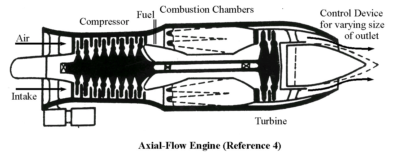 |
Axial-Flow Compressor Engine
(Reference 4) (Essential components indicated in full-size view) |
The axial-flow compressor is essentially a turbine in reverse with air flowing between
alternate rows of stationary (stator) and rotating (rotor) blades, each of aerofoil shape
(References 4 and 5).
Eventually, axial compressor engines would be developed which would allow higher
efficiency at lower frontal areas, so vital for aircraft, at some sacrifice to weight and
length.
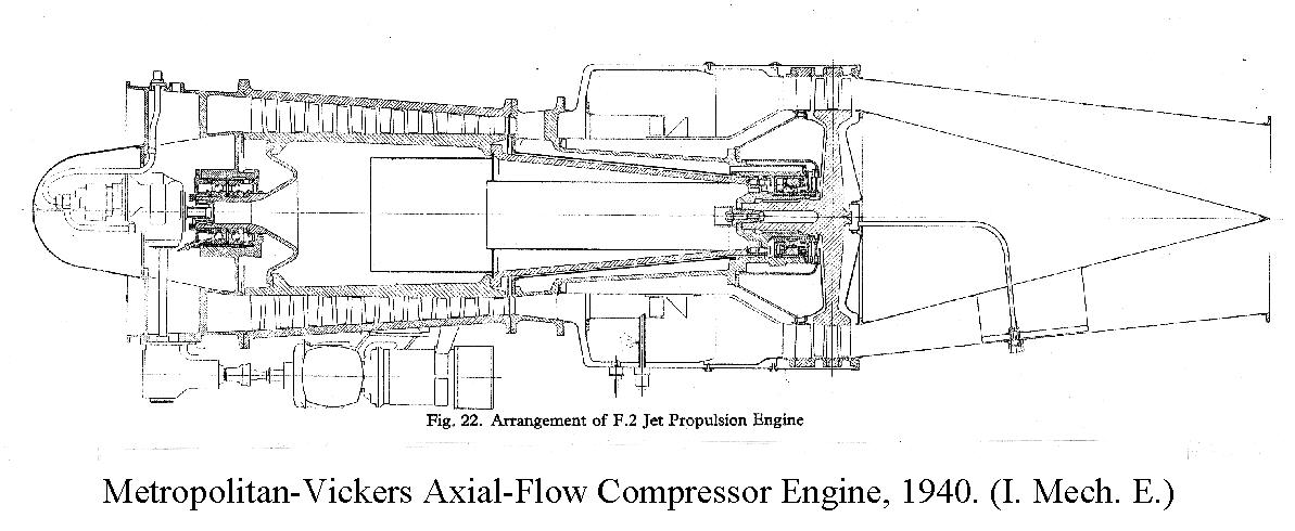 |
Metropolitan-Vickers F2 Axial-Flow Compressor Engine, 1940. (I. Mech. E.) | 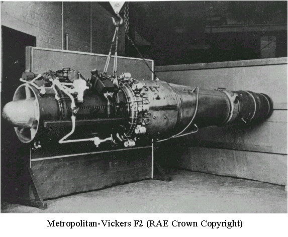 |
Metropolitan-Vickers F2 |
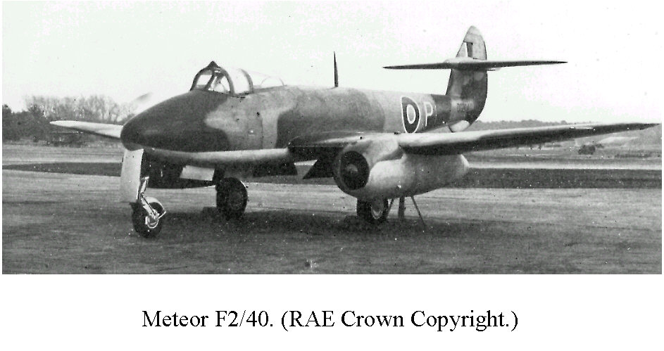 |
Meteor F2/40. (RAE Crown Copyright.) |
The Metropolitan-Vickers F2 (thrust rating 2,150 lb) first flew in the Meteor F2/40 in November 1943. This version never went into production. It was to be some years before British engines of this type were in service.
14. APPRECIATION BY SIR MELVILL JONES
Professor of Aeronautical Engineering
University of Cambridge, 1919-1952
(Whittle's Supervisor at Cambridge)
Frank Whittle came to Cambridge in October 1934. He was, at that time, a Flight Lieutenant in the RAF and he was the last of several such officers to be seconded from the RAF to study for our Mechanical Sciences Tripos. He was then aged about 27 and had been in the RAF since 1923, for the first 3 years in the apprentice wing at Cranwell* and, later, as a flying instructor and test pilot. From 1932 to 1934 he was at the RAF School of Aeronautical Engineering at Henlow. In 1936 he obtained a first class in our Tripos and then spent a postgraduate year developing his engine at the BTH works in Rugby.
Because of Whittle's special interest in aeronautics I was in close touch with him during the years he was in Cambridge. I always had a great admiration for him, particularly for the way in which he succeeded in getting a first class in our Tripos, after studying here for only two years. During this period he spent much of his time on jet propulsion, a subject which was not at that time included in the Tripos.
In those early days it was not easy to get support for extensive work on jet propulsion because, at the cruising speeds then prevalent, it would not be expected to operate very efficiently. I think therefore that it is greatly to Whittle's credit that he was able to foresee that, with jet propulsion and with still further improvements in the stream-lining of aircraft, the cruising speeds could be increased to values at which the jet would operate more efficiently than the conventional airscrew.
From what we now know about jet propulsion there can be little doubt that it would, in any case, have been developed eventually. But from my memories of those days I feel sure that without Whittle's enthusiastic pioneering work its coming, at least in this country, would have been delayed for several years. I have therefore no doubt that Whittle will be regarded by future historians as one of the important pioneers in the development of aviation.
* Sir Melvill omits to mention here that Whittle was awarded a cadetship at RAF College, Cranwell in 1926.
** Sir Melvill's memory is slightly at fault here. Power Jets Ltd. was formed before Whittle took the Tripos, actually in March 1936.
15. THE WHITTLE LABORATORY
Sir Frank Whittle's contribution to jet propulsion is commemorated by a research laboratory named after him. The Whittle Laboratory, which is an integral part of the University Engineering Department, specialises in the research of compressors and turbines. It was built with money given by the Science Research Council and opened in1972.
HAWTHORNE (Sir William). The early history of the aircraft gas turbine in Britain. (Notes & Records, Royal Society, London, 45, 79-108, 1991.)
CONSTANT (Hayne). The early history of the axial type of gas turbine engine. (Proceedings, Institution of Mechanical Engineers, 153, 462-472, 1945.)
H. Cohen, G. F. C. Rogers and H. I. H. Saravanamuttoo, Gas Turbine Theory, 4th Edition (Longman 1996, ISBN 0 582 23632 0)
17. INTERNET and OTHER REFERENCES/LINKS
Chronology: Compiled and Researched by Ian Whittle, 2010.
Obituary: Sir Frank Whittle. The Daily Telegraph, 10th August 1996.
Obituary: Hans von Ohain. The Guardian, 17th March 1998.
Coventry and Warwickshire Network: People File (Sir Frank Whittle)
Rolls-Royce History (Welland Engine, Timeline 1940-1959)
Peterhouse Sir Frank Whittle's Cambridge College
Churchill Archives Centre, where the Whittle Papers are held. The Churchill Archives Centre is happy to answer any queries about the Whittle Papers or provide an electronic copy of the full catalogue upon request, and can be contacted at archives@chu.cam.ac.uk.
Copyright Cambridge University Engineering Department 1998.
Crown Copyright is reproduced with the permission of the Controller of Her Majesty's Stationery Office.
Photographs: Royal Aerospace Establishment. Crown Copyright.
| Photographs and diagrams from the First James Clayton Lecture (Proceedings of the Institution of Mechanical Engineers, vol. 152) are reproduced by courtesy of the Council of the Institution. |
Correspondence to: The Secretary, CUED, Trumpington Street, Cambridge CB2 1PZ, UK.
Web pages devised and compiled by K.C.A. Smith, K.A. Knell and B.C. Breton (Cambridge, Easter Term 1998).