|
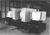
SPECIFICATION Acceleration: 175 gravities Payload: 1000kg (2250kg at 70 gravities) Radius of arm: 4.3m (at specimen) Power: 225kW Weight of unloaded rotor: 15 tonnes Click on image for detail |
 |
GEOTECHNICAL CENTRIFUGES
by
Philip Turner
The behaviour, including the failure modes, of any structure or material which is dependent upon its self-weight, can be simulated on a reduced size and/or time scale if it can be subjected to an acceleration greater than the ordinary gravitational acceleration. Then, of course, the mass is unchanged but effectively the weight is increased in the ratio of the accelerations. In practice this provides a powerful and extremely useful method of researching and testing such structures. If strictly uniform conditions are required, this can be achieved using straight-line acceleration as in a rocket-propelled sledge. The duration of the experiment is in this case strictly limited! But if some non-uniformity of the acceleration field and, for a moving specimen, some coriolis effects can be tolerated, a centrifuge is a much more convenient and adaptable device. When required, tests lasting many days can then be run.
A variety of these machines is to be found ranging from, for example, aerospace centrifuges generating a few gravities for evaluating the reaction of the human frame to the accelerations involved in space flight, to large geotechnical machines. Soil mechanics is indeed a particularly fruitful field of centrifuge application. Relatively large models of soil specimens, weighing up to a few tonnes,(dams, tunnels, oil rig foundations, river systems and so on, in addition to specimens for more fundamental research into soil properties) can be tested to hundreds of gravities. Such machines have come into prominence over the last 30 years or more and because of the unusual and demanding specification required, many have been purpose-built to suit a specific area of soils research.
At the request of the Cambridge University Department of Soil Mechanics and Andrew N.Schofield and Associates Ltd., I designed two large machines for this purpose (and made design studies of many more proposed machines) both of which are of novel configuration and incorporate some innovative features. The first is an arm centrifuge of which the salient features are described in the write-up and figures which follow. If, as seems reasonable, the 'capacity' of a centrifuge is measured by the product of radius, acceleration and payload, this machine, when first built, was among the geotechnical machines having the largest capacity then available and has provided the basis for the design of other similar machines, notably by the Japanese.
The second machine is a drum centrifuge. A summary description and a drawing of this are included. Both of these machines are installed in the Schofield Centrifuge Centre of Cambridge University Engineering Department, West Cambridge Site. The arm centrifuge was designed and built in the early 1970s and the drum centrifuge in the 1980s. Both have been in virtually continuous service until the present time. In these pages the design aspects of the two machines are described; applications of the machines are described elsewhere by Professor Andrew Schofield and others on the Geotechnical Research Group's web pages.
THE ARM CENTRIFUGE
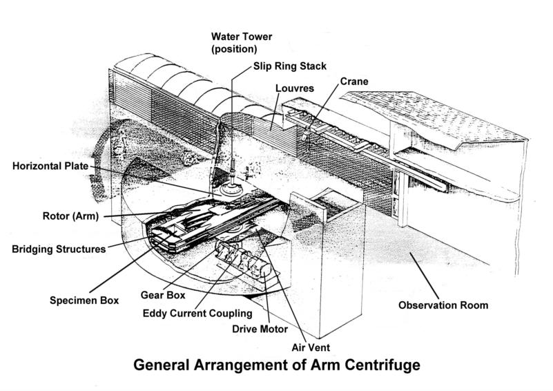
This machine consists essentially of a beam-like structure or arm, which rotates about a central vertical axis. (See drawing of general arrangement.) The specimens are carried at either end of the arm. In normal operation these are contained within strong boxes, so called because the forces generated within the box by the specimens when the centrifuge is spinning can be large. The stresses can in fact be equivalent to filling the boxes under normal gravity with a liquid having a density forty times that of mercury. The outline specification of this centrifuge is given below.
General Arrangement
|
SPECIFICATION Acceleration: 175 gravities Payload: 1000kg (2250kg at 70 gravities) Radius of arm: 4.3m (at specimen) Power: 225kW Weight of unloaded rotor: 15 tonnes Click on image for detail |
|
The centrifuge is housed in a squat cylindrical reinforced concrete shell 3m deep and 14m in diameter and, since the energy released in a structural failure could be as much as 107 joules, the rotating parts are positioned well below ground level. The peripheral walls of the cylinder are 1m thick and the heavily reinforced sections towards the axis of the centrifuge are designed to sustain a short period rotating force of 225,000kgf. In the event of one specimen package becoming completely detached during a test, this will enable the out-of-balance centrifugal forces to be contained until the centrifuge can be brought to rest. Dr Chris Morley of the University Engineering Department designed the appropriate complex and sophisticated reinforced concrete structure to achieve this. Below the cylindrical shell is a tunnel in which the drive unit is mounted and which also communicates with a vertical air duct. Two vents, one being farther from the axis of rotation of the centrifuge than the other, are so positioned that, in effect, part of the rotor arm itself forms the impeller of a centrifugal air pump causing air to flow in through the louvres, along the tunnel and out to atmosphere through the duct. About 225kW may be dissipated by the rotor arm in the pit and a maximum increase in cooling air temperature of 5� C has been permitted. The area of one vent is variable in order that the airflow may be adjusted. It is undesirable to use an excess of cooling air because of the power that this will absorb. The powerful downward airflow in the pit and the working area above it quickly removes dust, which otherwise can be troublesome, from these spaces. The inner concrete surfaces of the pit are protected with a thick epoxy paint against the abrasive effects of high velocity dust particles.
A vertical access shaft leads to the drive unit and its accessories, and at the lowest part of the tunnel an automatic sump pump removes water which may enter through weep holes in the concrete shell.
Above the cylindrical shell a layer of soil provides added safety, balances air pressure due to the spinning air body within and prevents buoyancy effects which conceivably might cause the entire concrete vessel to float out of the ground in near flood weather conditions! A corridor 2m wide runs diametrically across the rotor pit and is separated from it by a floor clad with 10mm steel tread plate designed to contain objects which may become detached from the rotor. In this floor, access, observation and instrumentation hatches are positioned, and mounting frames for measuring devices etc. are provided immediately above floor level. Signal, control and power lines from the 80-element slip ring stack and the hydraulic lines are routed along this corridor to the control and observation rooms and an overhead crane enables prepared specimen packages to be transported and mounted into the rotor arm. The corridor is roofed with translucent glass-reinforced plastic.
Rotor
In order that the rotor should be conveniently constructed in the Department's workshops, it was necessary that it be made in relatively small, easily handled and assembled sections. Also cost considerations ruled out the more exotic materials. Further, so that the specimen strong-box design, construction and mounting could be simplified, it was desirable to bring the main arm structure round the back of the specimen box in a "sling" configuration. After much consideration of alternative structures it was decided to use the arrangement illustrated in the drawing, with all the site joints made by means of friction grip bolts. A degree of redundancy in this structure makes it fail-safe and the use of friction grip bolts enables relatively large dimensional tolerances to be accommodated. The rotor can be broken down into the following components:
1. Four principal structural members of hollow rolled section steel, approximately 400 x 200mm cross-section (16x8 inch standard imperial size) about 10m long and having gusset plates welded to them over their central section for attachment to the bearing shaft assembly. Parts of these welds are critically stressed, and for this reason the welding was undertaken by the then Welding Institute, at Abington, Cambridge. A special welding machine was constructed to weld the gusset plates onto the spokes. The machine was designed to reduce thermal notching to an absolute minimum. The welds were heat treated, shot-peened and polished.
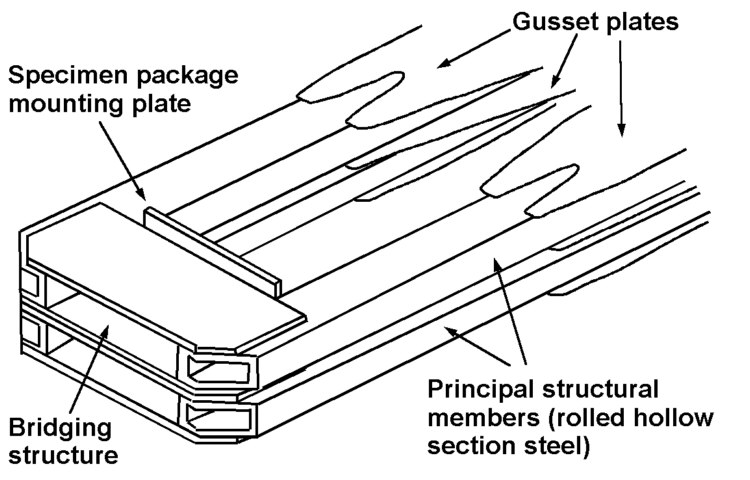 |
Structural Members and Bridging Structure |
2. Two bridging structures linking the ends of the structural members and bolted to them. The line of' attachment of' the bridge to the structural members is arranged to be off the centroidal line of the latter so that the resulting flexure of the members matches the flexure of the bridge and reduces the moment across the joint thus ensuring equal stressing of all bolts. A quarter-scale model of this assembly was fatigue tested to destruction in the laboratory. The number of cycles to failure agreed well with the predicted value.
The specimen package mounting plate is an integral part of the bridge structure and is slightly offset downwards so that at maximum 'g' the resultant of centrifugal and gravity forces generates no bending moment at the centre of the rotor arms, which are thus in simple tension at the point where the centrifugal forces are greatest.
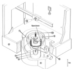
3. A fixed specimen mounting plate which enables the full capacity of the centrifuge to be utilised, but of course subjects the specimens to a vertical gravitation force during loading when the centrifuge is stationary. For this reason an alternative swinging carriage mounting is provided. The platform on which the specimen is mounted is hung on two swing arms from pivots at their upper ends. These pivots are themselves free to move in a radial direction against the restraint of links and torsion bars, thus allowing the swinging platform to seat on the fixed mounting plates when the force on the pivots reaches a pre-determined value.
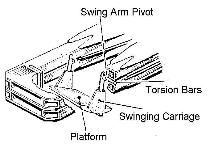 |
Swinging Specimen Carriage |
As the centrifuge is accelerated from rest, therefore, the carriage will swing into the operating position where it is restrained by a stop. During this operation forces in the specimen will always act substantially perpendicular to the base of the specimen. Increasing centrifugal force will then cause it to seat on the fixed plates after which point it becomes effectively solid with the rotating structure and there is no further increase in the forces in the swing arms. Satisfactory seating is indicated by electrical contacts. Such an arrangement allows a relatively very light carriage to be employed since the forces in it are reduced by a factor of about 20 compared with a fixed pivot device. The platform is of relatively complex shape and was machined out of the solid from aluminium alloy on a numerically-controlled milling machine.
4. The hollow central bearing shaft, which is turned from a solid blank 0.6m in diameter and 2m long, and which carries at either end a self-aligning spherical roller bearing. The entire gravity load is carried by the lower bearing, which is directly attached to the concrete foundations through a rigid mounting structure. The upper bearing is mounted to the concrete structure on a relatively thin horizontal plate, thus allowing axial float by flexure of the plate. With this arrangement no unknown forces due to misalignment, settling, differential expansion or inaccurate fitting can be exerted on the bearings. For the same reason a resilient coupling is used to connect the rotor shaft to the drive unit.
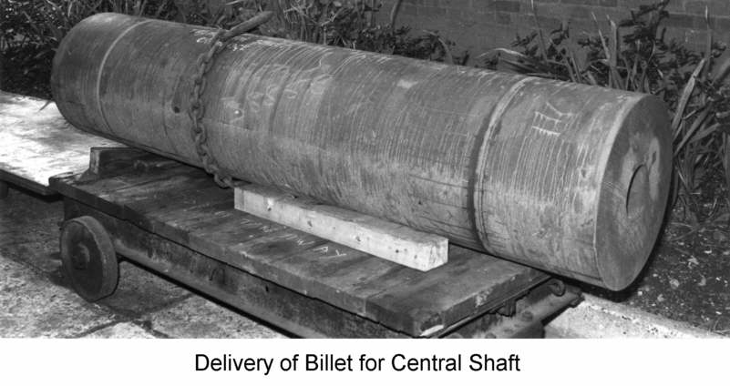 |
Billet for Central Shaft | 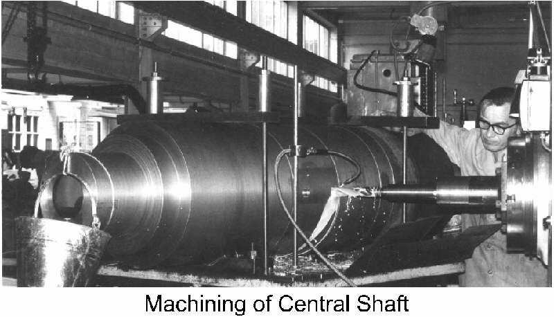 |
Machining of Central Shaft |
A considerable clearance was provided between the rotor arm structure and the bearing shaft. After assembly and careful alignment of the axis of the rotor with the axis of the shaft, this clearance was filled with Loctite high strength retaining compound. This technique, combined with friction grip bolting, reduces locked-up stresses to a minimum and considerably facilitates accurate assembly.
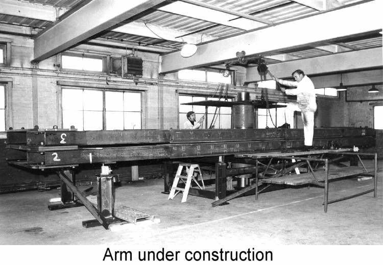 |
Arm under constuction |
Design stress levels and material were determined by, firstly, fatigue requirements and, secondly, ultimate loading requirements. The former must allow at least 10,000 start-full load-stop cycles corresponding to at least 10 year’s operation, or under more typical operating conditions, a fatigue life very much in excess of this. The latter required that the structure should have adequate safety factors on static and centrifugal loadings and should not fail under extreme out-of-balance, such as the loss of one specimen package under full `g' conditions. High yield steel to BS4360 Grade 50C was found to have a small overall advantage over mild steel and consequently was selected for all the components of the rotating structure. The total weight of the rotor is about 15 tonnes.
Above the upper bearing an extension of the shaft carries the slip-ring stack, comprising 4 hydraulic or pneumatic rings, 4 power rings (i.e., 3-phase A.C. and earth) and 80 low-noise signal rings. The rotor is earthed through a slip ring since it was considered that under some atmospheric conditions a static charge might otherwise accumulate on it, to the detriment of the bearings and instrumentation.
 |
Central Shaft fitted to Arm and mounted in housing | 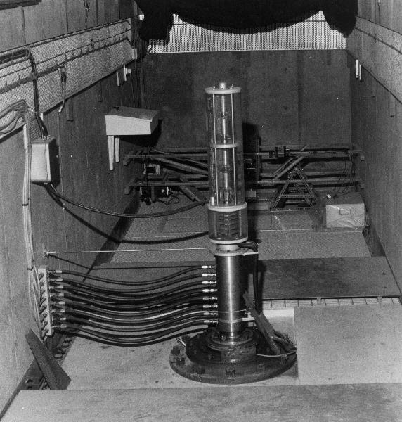 |
Slipring Stack |
Power Requirements
One of the most intractable problems arising in the design of a centrifuge is the estimation of the power required to drive it, particularly when it is of novel aerodynamic design and considerably larger than any existing centrifuge for which data is available. Three different approaches were made.
1. A plot of suitable parameters was made for centrifuges for which it was possible to obtain the necessary information. These plots exhibited a large scatter and application to the Cambridge centrifuge involved considerable extrapolation. Therefore the results were to be considered as nothing more than a very rough guide.
2. A purely theoretical approach was made by assuming that the spinning air body in the pit rotated en masse at least over the more significant outer part of its radius. Expressions could then be derived for the torque generated by the relative motion of, firstly, the rotor arm and the air body and secondly the air body and the pit.
These could then be equated and hence the torque on the rotor calculated. This method appeared to provide useful results. It predicted powers in fair agreement with 1 above and the model described in 3.
3. A rig was constructed in which a wooden model of the rotor arm could be spun inside a hollow cylinder suspended on a torsion wire. The rotation of the latter allowed the torque on it to be measured. For practical reasons the model could not be larger than 1/12 scale and hence extrapolation of the results to the full-scale centrifuge involved considerable uncertainties. However, these results were considered to be more accurate than those obtained from methods 1 and 2. Investigation of the effect of the shape of cross-section of the rotor arm was carried out including the effect of a highly streamlined fairing, of holes and slots and of sharp edges. Also such factors as tip clearance and vertical clearance between rotor and pit, roughness of the pit wall (by using various grades of sandpaper to simulate the pit wall) and contour of the pit wall were looked at.
These considerations enabled a reasonable compromise to be reached between aerodynamic and structural requirements. For example, the rotor arm although flat and blade-like had no fairing (although a fairing was subsequently added and found to have a marginal advantage); the pit wall, although smooth, is polygonal rather than circular. With regard to absolute power requirements the tests and calculations indicated that 175g should be reached with around 225kW. It would have been desirable to have increased this figure in order to take care of uncertainties, but such an expedient would have been too costly. In fact the 225kW drive unit fitted was found to provide an acceleration of nearly 170g.
Drive Unit
The drive system selected consists essentially of a constant speed 225kW A.C. electric motor driving the rotor through a water-cooled eddy current coupling and worm and wheel gearbox. The cooling water is passed through an external cooling tower. The eddy current coupling also serves as a brake. Such a system is moderate in first cost, easily controlled, has low starting current and is economical in running costs for an application where high torque coincides with low slip and vice versa. It also generates a minimum of electrical interference which is an important consideration in a system having numerous and lengthy low-signal circuits.
|
|
Drive Unit |
The lay-out of the drive unit is shown in the general arrangement drawing. An electromechanical friction brake is interposed between the motor and the eddy current coupling and a similar brake between the coupling and the gearbox. To start the centrifuge the motor is run up to speed unloaded. The coupling is then energised so as to provide a predetermined constant torque until the selected operating speed of the rotor is reached. This speed is then held to a nominal value of plus or minus one quarter of one percent for the duration of the test run. Provision is also made for a programmable variation in speed. To stop the machine the eddy current coupling is de-energised, the motor stopped and locked by means of the first friction brake. The coupling is then re-energised to give a constant torque slow down, the energy being dissipated by the forced draught cooling tower, until a speed is reached at which the coupling becomes ineffective. The second friction brake then takes over to bring the rotor to a standstill. The sequence of operations is fully automatic and the machine is provided with comprehensive safety devices to shut it down in the event of a malfunction and to ensure the safety of the operating personnel.
Modifications and additions
The swinging specimen platform was added after the machine had been operating for some months with the fixed platform only. After the need for a swinging platform became apparent, the first thought was to cut off the end structures of the arm and to replace them with conventional massive hinges carrying the swinging platforms. As many designers will know to their cost, such radical surgery to a finely-tuned design always presents uncomfortable problems! In this case a brief design study was all that was necessary to indicate that a completely new arm would be the only satisfactory approach to the conventional hinge solution. This was unacceptably expensive and time-consuming. So, as often, the lack of money and time were the parents of invention. The patented arrangement described above under Rotor, section 3, was the outcome.
A further innovative later addition was an earthquake simulation facility. This causes the specimen to be given a substantial tangential (i.e., horizontal and perpendicular to the length of the arm) vibration while in flight, in order to simulate an earthquake. The design problem here is the magnitude of the forces and energy involved. The required tangential specimen acceleration may be as high as 50% of the radial centrifugal acceleration, so that for example with a 350kg specimen package running at 100 gravities the force required is 17,500kgf. The amplitude at lower acceleration may be as much as 10mm and the maximum frequency 100Hz. The short - term power requirement for a sustained, as distinct from an impulsive, motion depends, of course, on the damping of the system (mostly due to specimen deformation) and may be measured in hundreds of kilowatts. Additionally maximum amplitude must ideally be built up over the first vibration cycle and, preferably, it should be possible to generate variable frequency and non-sinusoidal wave forms. Also repeated operations are required during a given test run. The actuators have to be of low weight in order not significantly to reduce the payload and of course be able to operate in a high-g environment. This is a demanding specification. Having looked at hydraulic, pneumatic, electromagnetic, piezoelectric and motor-driven actuators, and the use of explosives, it was clear that either these could not meet the required specification or that development problems could not be overcome, at least with the facilities and time available. The arithmetic was against them and mathematics is not negotiable.
In this situation a more fundamental approach is necessary. The basic need is for a large but short-term source of useable energy and one which adds little to the weight of the rotating system. What about the rotating system itself? There is a relatively very large amount of energy stored in the spinning rotor. Would it be possible to siphon off some of this in order to power the earthquake? Some quick calculations showed that the energy to power a single earthquake was almost negligibly small compared with the total kinetic energy stored in the rotor. This was promising. The tiny reduction in angular velocity of the rotor would have a negligible effect on the specimen during the event. The problem now was how to utilise this energy. There are many possibilities, none of them straightforward, but after some feasibility studies, my final choice was a simple cam and follower system. The cam is fixed to the wall of the pit and extends for about one third of its circumference. It consists of a deep solid steel beam, 50mm thick, having the required wave form machined on its inner edge. Alternative cams can be used to generate alternative wave-forms. The follower and its associated mechanism are carried on the end of. the centrifuge arm. It is made up of a small (about 200mm diameter) light alloy wheel with a solid pre-stressed nylon tyre mounted on one arm of a bell crank. The other arm of the bell crank is connected by a lever and variable stroke cross-head mechanism to the specimen package which can slide on linear roller bearings on the arm platform. A pneumatic actuator holds the wheel clear of the cam while the centrifuge is run up and instrumentation, cameras etc, prepared. The actuator is then operated to force the wheel into contact with the cam for a single transit of the latter after which the wheel is retracted. The whole cycle of events is completed in a fraction of a second. For obvious reasons this system has become generally known as a "bumpy road" actuator. Typically the amplitude of vibration at the wheel is 10mm, the frequency 100Hz and the calculated peak force on the wheel in excess of 250kgf. The maximum "touch-down" velocity of the wheel on the bumpy road cam can approach that of the touch-down velocity of a jet aircraft. Although rough energy dissipation and stress calculations showed that the light-weight nylon-tyred wheel should survive this treatment for a few hundred operations, one still has an irrational feeling of surprise that it actually does! The original wheel is still in use after more than 1000 earthquake tests. The most difficult problem in designing the moving part of this system was in making its stiffness/inertia ratio high enough to put its natural frequency, when coupled to the relatively massive specimen, above the frequency of earthquake excitation. In practice significant degradation of the waveform has to be tolerated for this reason but nevertheless a useful earthquake can be generated.
A useless but intriguing piece of information came to light out of calculations which I made to check that gyroscopic forces on the centrifuge rotor due to the Earth's rotation were negligible. They were. But it transpired that if, by way of illustration, the centrifuge is started at 6 o'clock in the morning and stopped at 6 o'clock at night, the length of the day is reduced by, give or take a few orders of. magnitude, 10-30 seconds due to transfer of angular momentum from the Earth to the centrifuge and back again. We all live a little longer as measured by the rotation of the Earth!
THE DRUM CENTRIFUGE
 The
second machine, illustrated in the outline drawing, is designed to accommodate
specimens and models of a very different shape, which may be liquid, semi-liquid
– as for example wet clay – or solid. Essentially, these specimens
have a relatively large area but a small depth along the direction of the acceleration
field. The centrifuge has the form of a hollow drum on the inner surface of
which the specimens are carried rather in the fashion of the washing in a domestic
spin dryer – although of course the magnitude of the quantities involved
is hugely different since this machine carries a payload of two tonnes at an
acceleration of 500 gravities!
The
second machine, illustrated in the outline drawing, is designed to accommodate
specimens and models of a very different shape, which may be liquid, semi-liquid
– as for example wet clay – or solid. Essentially, these specimens
have a relatively large area but a small depth along the direction of the acceleration
field. The centrifuge has the form of a hollow drum on the inner surface of
which the specimens are carried rather in the fashion of the washing in a domestic
spin dryer – although of course the magnitude of the quantities involved
is hugely different since this machine carries a payload of two tonnes at an
acceleration of 500 gravities!